
Project Ultimate 83 GTI
Engine, Oiling, Cooling, Transmission & Exhaust Systems ...


Engine
This is a very special one-of-a-kind normally aspirated engine that can be driven on pump gas, idling smoothly at 1000rpm, producing usable torque from 1500rpm+ with a flat torque curve all the way up to 6500rpm and peak power extending past 8000rpm. There are no pulley driven accessories to rob horsepower (electric water pump & A/C compressor, manual R&P steering, 50amp racing alternator with WOT disconnect – this is one of the reasons the 2.1L motor puts out close to 250hp at the crank – at least 15hp is saved by keeping parasitic power losses to an absolute minimum).
And this engine is light weight in comparison to a VR6 or a later model turbo engine setup. In comparison to the original 90hp Mk1 GTI engine this combination produces more torque at all rpms and puts out 3 times the power – but at a high enough rpm that if you don’t want the buzzing rpms you can simply keep the revs below 5000rpm and enjoy a more stock-like street driving experience. The ITBs are large as they are optimized for high rpm power production so the throttle is a bit sensitive in comparison to the OEM engine but it is a learned behaviour to be a bit cautious about throttle inputs – and if you keep the rpms down it really does tame the engine, generating a more relaxed driving experience when you are not in the mood to accelerate with 0.6g of force at >100kmh:
240hp @ 7250-8000rpm, catalytic converter and air box removed
220hp @ 7000-7400rpm, with catalytic converter and air box/filter installed
Mk3 ABA tall-deck block, 2092cc (83.5x95.5mm) w crank position sensor
ARP rod bolts, head studs & crank sprocket M16 bolt w dowel pins
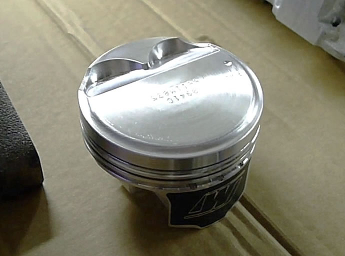
11.5:1cr forged Weisco pistons
Rotating assembly dynamically balanced
Mk2 9A 16V heads (34mm x 5.5mm stem intake valves, 29.5mm x 7mm (6.5mm undercut) stem exhaust valves), extensive porting and polishing
288° Cam set - solid lifter (254° @.050", .456" lift, 105° LC)
4% leakdown test results on all cylinders – perfect!
Adjustable cam sprocket, cam position sensor
DLC coated solid bucket lifters
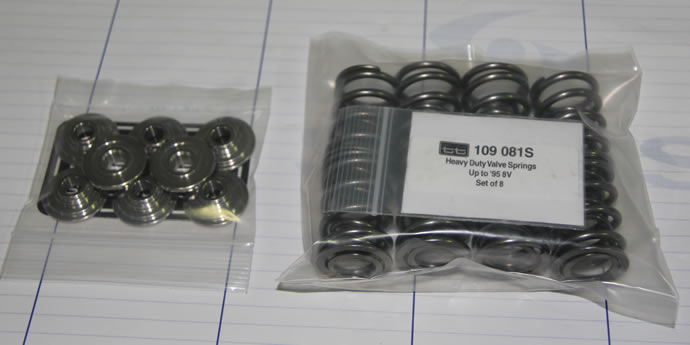
VR6 HD valve springs
Titanium retainers
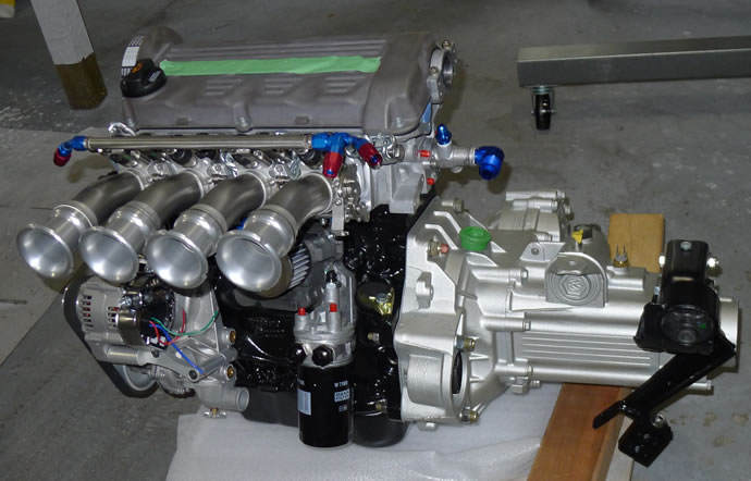
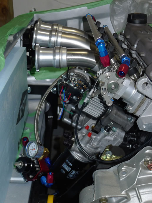
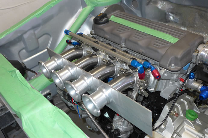
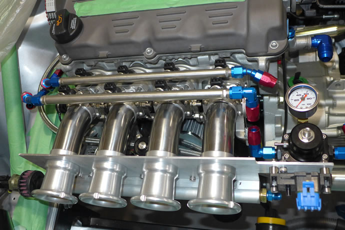
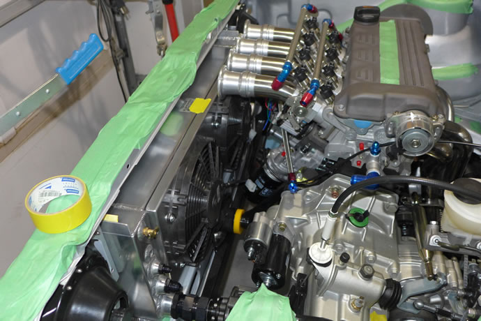
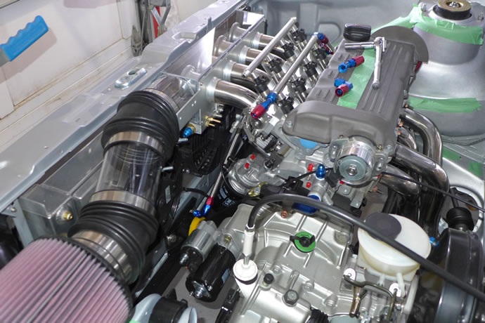
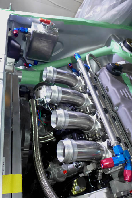
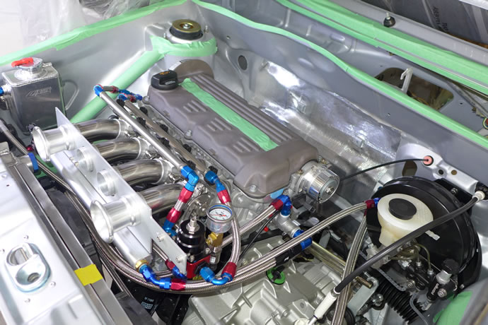
45mm tapered/curved independent throttle bodies (ITBs)
Dual rail 19lbs/hr x 4, 30lbs/hr x 4 fuel injectors (idle-low speed, high power)
All stainless steel braided fuel lines and fittings
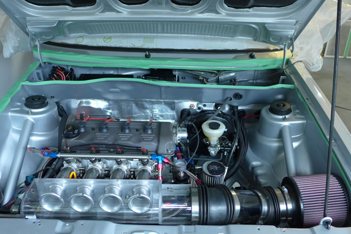
Lexan air box with K&N filter
Digital idle speed control
4 port PWM ECU controlled nitrous system, 25-100hp, adjustable
Holley Dominator ECU & ignition system
8.5mm custom length racing ignition wires
Denso IK20 spark plugs
Billet aluminum alternator bracket
Racing damper, serpentine alternator belt
Racing 50amp alternator, ECU controlled output voltage
Solid rubber engine mounts (will never wear out but also keeps vibration down)
The background story on the engine ...
I was always interested in Callaway turbo kits for my original GTI and came close to acquiring an 84 GTI with one of these kits installed on it. But turbo kits add weight and they change the engine's free revving characteristics which were perfectly matched to the 5 speed trans. For me in the early 80s the ultimate GTI was the 1982 Oettinger 16S GTI (only available in France and Switzerland in 1982) - lots of power and revs and very exclusive in its day. I feel that the ultimate mk1 GTI has carefully massaged 16V heads (keeping an eye on mid-range torque), a 2L block, and a close ratio 020 transmission. So I contacted Josh Arnold at Techtonics Tuning in Portland, Oregon, (who is actually doing the engine development work at his own business with his dad, Mark (Mark's VW Service, Amity, Oregon) and asked him if he would do the ultimate 16V buildup. He started sourcing the components and building up the motor in late November 2012 and completed it in March 2014 (for more info on Josh, TT, and a similar project, see this VWVortex thread).We choose a VW/Audi ABA block (a US version of the European ABF tall-deck block used in the mk3 VW/Audi 93-97 16V 2L cars producing 150hp) and Josh built a 2092cc 16V motor using a new balanced VW Audi OEM 95.5mm diesel forged crank, balanced VW Audi 159mm forged connecting rods, 83.5mm 11.5:1cr Weisco pistons p/n 6611M835 (11:1cr with 92.8mm stroke in a 9Aor PL block) and a balanced intermediate shaft.For those of you who are interested in the math of how this all works, the block height of an ABA/ABF block vs a 9A/PL block is 6mm taller (236mm vs 220mm) but the rods are only 5mm taller (159mm vs 144mm). The stock ABA pistons have a 30.6mm compression height while the 9A/PL pistons are around 29.8mm. The 95.5mm diesel crank has a (95.5mm-92.8mm)/2 = 1.35mm higher lift but rods are 1mm shorter and the 9A/PL pistons have a 0.8mm lower compression height, so all you need to do is deck a used ABA/ABF block 0.45mm and you are right on the money - the increased stroke raises the compression ratio to around 11.5:1 from 11:1 in a 9A/PL engine using the Weisco pistons.
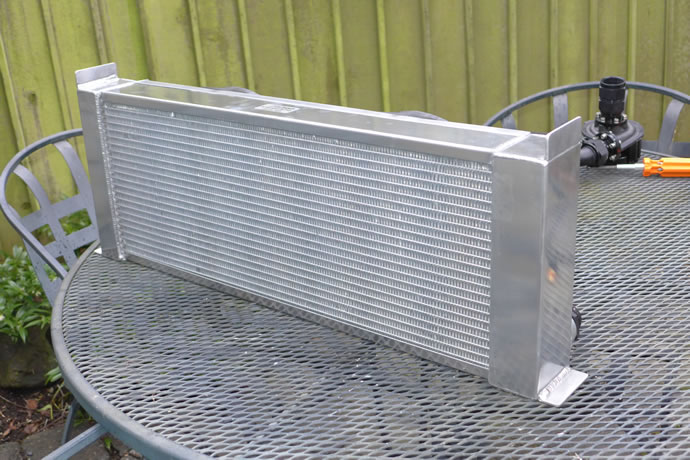
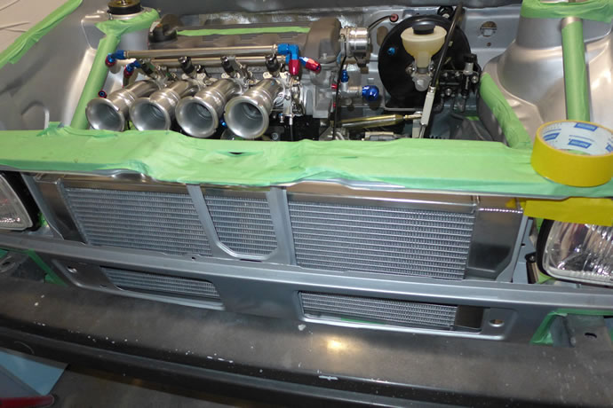
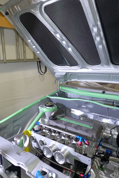
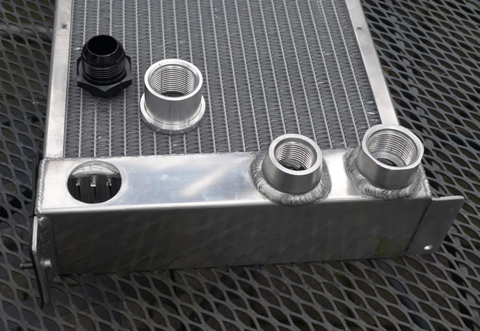
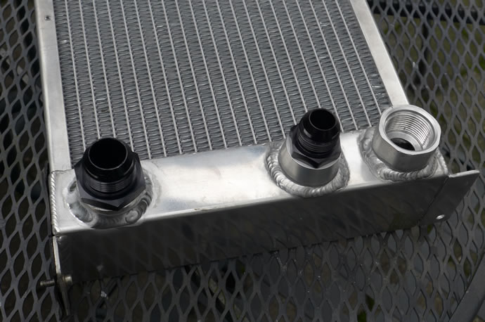
To fit in the ATPower ITBs and their long curved 280mm individual intakes, a custom radiatorhad to be designed that tucks in behind the grill.
Oiling System
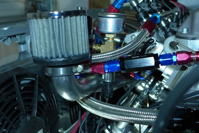
Keeping a high rpm, high compression engine properly lubricated with cool, clean oil is important. I ran a metal mesh filter back in the day with my first GTI and so it was nice to spec in a remote mount high flow K&N washable 25 micron metal mesh filter with a Mocal/Laminova oil thermostat and coolant intercooler – when racing at WOT on a hot day the engine oil temperatures might reach 230 degrees F which is great cooling performance, and on the street the oil temperature always stays in the range of 200-210 degrees F – the oil stays clean and the filter is easy to remove/clean as it is mounted below the radiator and is easy to reach:
16V 36mm/high volume oil pump and pickup tube
VW Mk3 motorsport windage tray
Full Synthetic 5W40 Joe Gibbs DT40 oil
Custom crankcase breather system
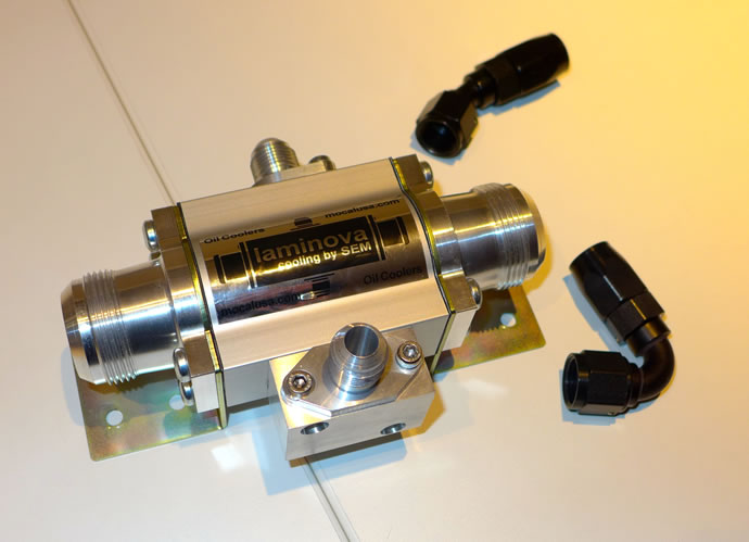
Mocal 200 degree F oil thermostat plate
Mocal/Laminova oil to coolant intercooler
K&N external oil filter with 25 micron metal mesh element
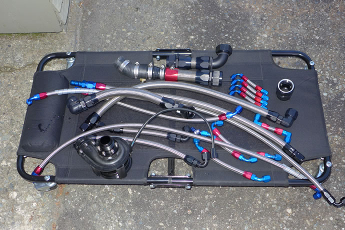
All stainless steel braided oil lines and AN fittings
Cooling System
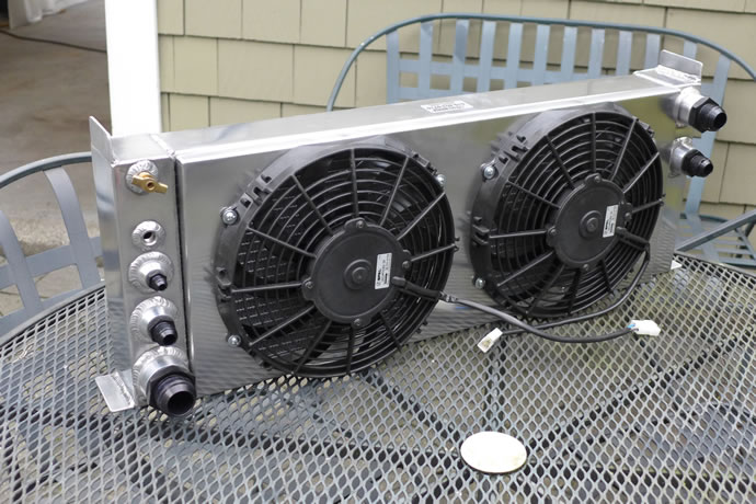
In order to make room for the long curved ITB intake runners the stock radiator had to be removed and a custom high capacity radiator e fabricated that would fit under the front cross member – the design includes two 10” Spal puller fans, one driven at 7V for low speed cooling when the radiator exit temperature reaches 170 degrees F, and the other fan driven at 13.5V for high speed cooling when temps exceed 180 degrees F – this setup works very well indeed.
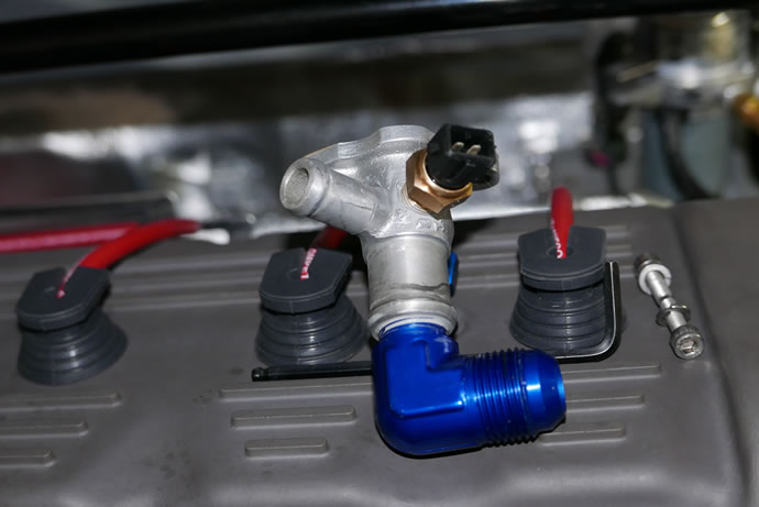
The electric water pump is an OEM quality unit that also works very well: the controller module varies the speed of the pump based on the coolant temperature and allows for programmable coolant temperatures – and it also provides for ‘engine-off’ cool-down by continuing to circulate the coolant while the ECU controls the Spal radiator fans – an excellent feature for high performance driving use.
Again, all stainless steel braided coolant hoses with AN fittings/coupling used throughout. A Canton coolant recovery tank mounted on the side of the engine bay near the front makes it easy to check and fill the coolant level.
Aluminum TIG welded custom racing radiator with AN fittings
2 Spal 10” puller fans (low and high speed, ECU controlled)
Electric water pump and digital controller (190 degree F setpoint for street use)
Aluminum TIG welded Canton Mecca coolant recovery tank
Stainless Steel braided cooling hoses and AN fittings throughout
Transmission
The original Mk1 and mk2 GTIs came with variants of the VW 020 5 speed close-ratio transmission which has a practical upper power limit of 150hp but it can be built to stronger specs to (barely) withstand a 200+hp engine if driven with some respect for the transmission. The 020 transmission is very light and compact so it keeps the weight down up front and it does utilize the original OEM mechanical linkage which is a unique aspect to these early Mk1 GTIs. The final choice was a Mk2 020-2Y 16V transmission with internal upgrades and California stage 3 and stage 5 clutches (street/race). The 020 mechanical shifter linkage remains in an updated state with heim joints and adjustable linkages, and an adjustable short throw shifter lever, for quick and precise shifts – old school, but really nice as an alternative to more modern cable-shift systems:
Hardened gear sets
ARP pinion gear fasteners
3.67 final drive (16V) ratio
0.76 5th gear swap
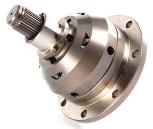
Quaife limited slip differential
California Clutch 1800lbs pressure plate, 6 puck stage 5 clutch disk, dynamically balanced
ARP pressure plate bolts
100mm output flanges
500hp rated axles with XL splines/hubs/12mm stud conversion
USRT clutch cable termination hardware
USRT heim joint adjustable shift linkages
Solid rubber transmission mounts (will never wear out but also keeps vibration down)
Exhaust System
Achieving the right balance of power & torque while also ending up with a nice mellow sound and longevity requires moderate stainless steel pipe sizing and lots of race-spec stainless resonators. After years of racing and designing exhaust systems I have learned the art of efficient, quiet exhaust system design (the exhaust is not ‘quiet’ by street car standards, but is very quiet by race car standards – it sounds very serious but not irritating on the street, especially with the catalytic converted installed):
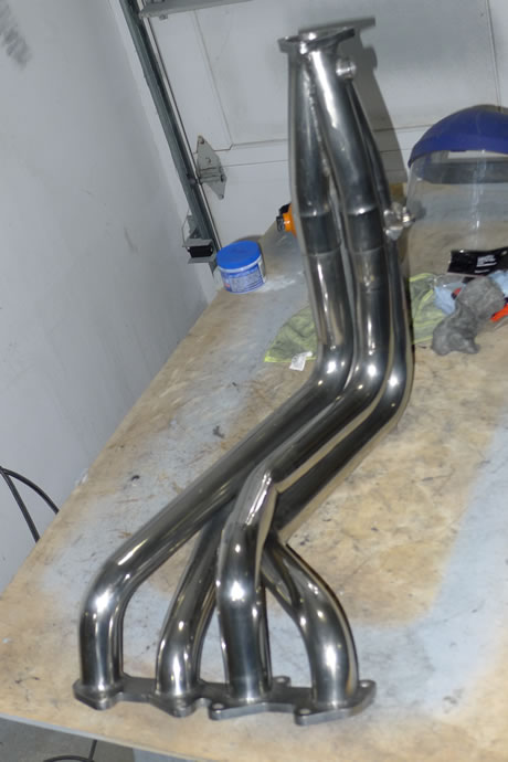
Custom 1.75” primaries race header for tall-deck block, stainless steel
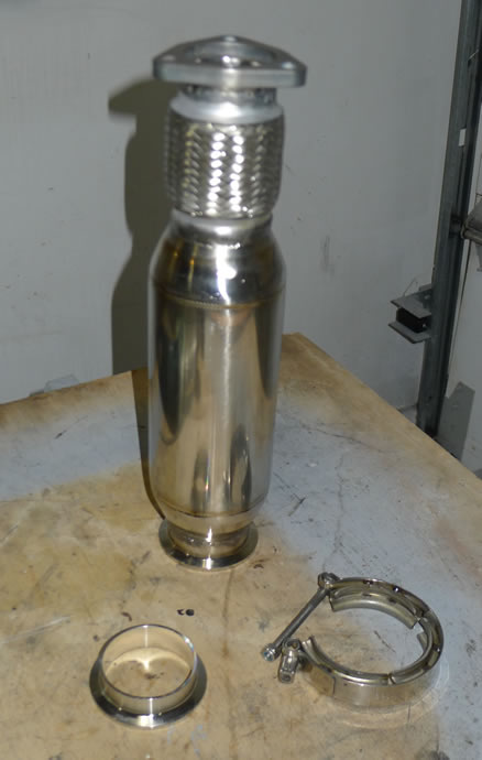
Vibrant stainless resonator or highflow catalytic converter with flex pipe
Quick-connect stainless steel couplings
Tectonics tuning 2.25” cat-back exhaust system, stainless steel
Borla stainless steel rear resonator/muffler
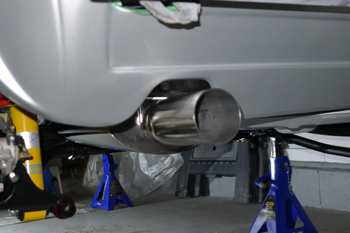
2.5” custom stainless steel exhaust tip
The timeline story of the engine and transmission building process
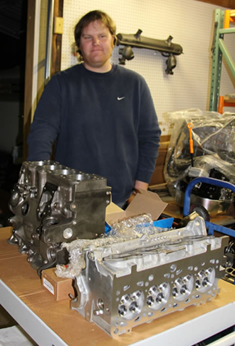
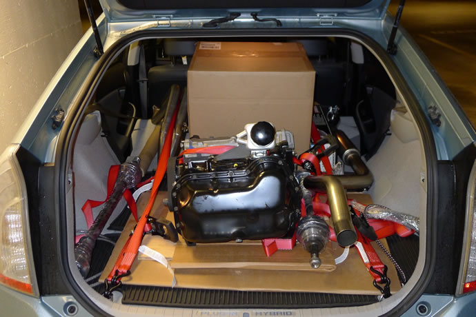
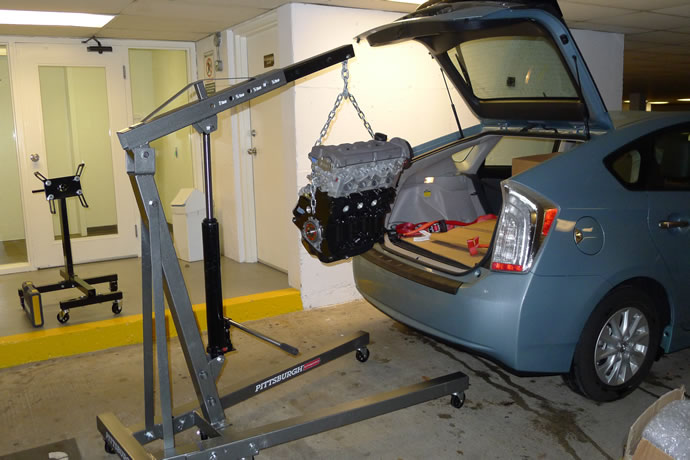
Initial Engine Assembly photos - taken at Mark's VW Service and Techtonics Tuning - Feb 15, 2013
Josh Arnold - engine builder extraordinaire
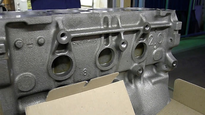
The VW (mk3) ABA block, (mk2) 9A cylinder head and 83.5mm forged piston
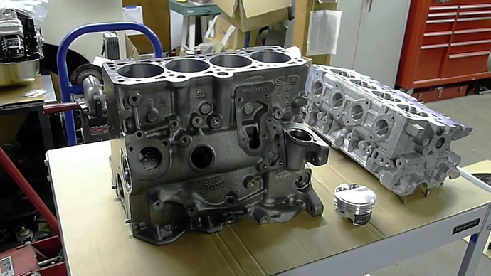
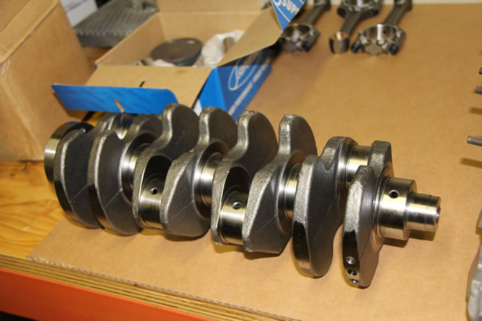
95.5mm stroker VW forged crank and rods prior to lightening and finishing
11.5:1cr forged 12% silicon (low expansion) forged piston
VW 9A 16V cylinder head
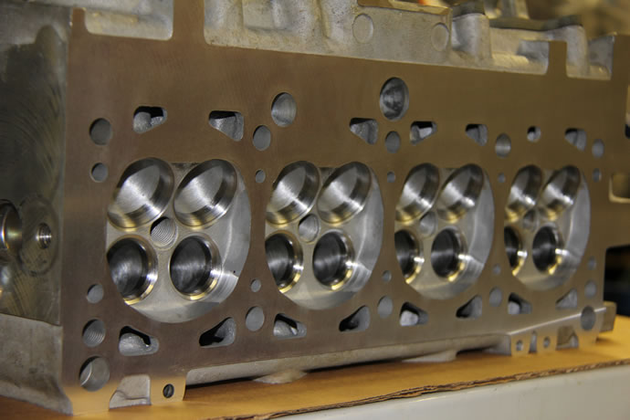
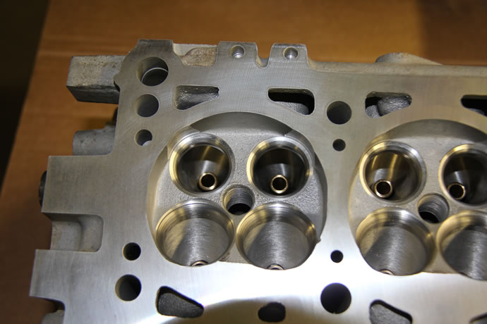
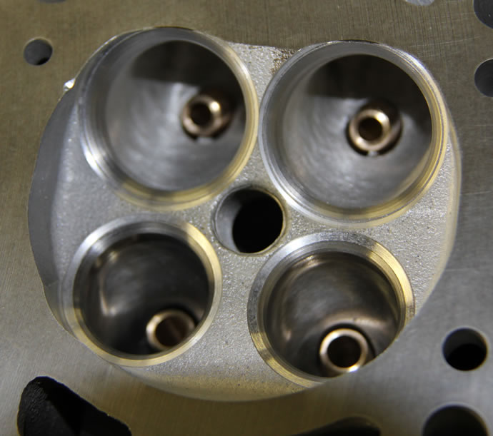
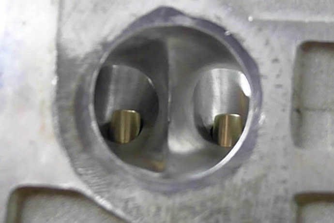
Combustion chambers with 34.0/29.5mm oversized valve seats, prior to blending, valve unshrouding and bore matching
Intake ports (left unpolished to foster mild turbulance)
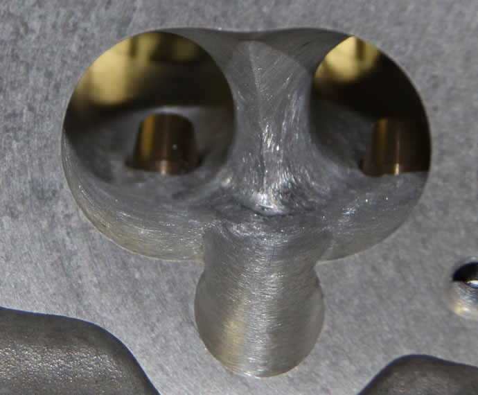
Tapered 5.5mm intake valve guides and blended 34.0mm (+2mm) valve seats
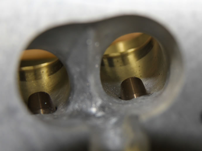
Polished exhaust ports, tapered exhaust valve guides, 29.5mm (+1.5mm) valve seats, port matched to 1.75" primary exhaust header tubes
Comparison of 5.5mm stem x 34.0mm diameter intake valve with stock 7.0mm stem x 32.0mm diameter intake valve and retainers

Comparison of 29.5mm diameter light weight/undercut exhaust valve with stock 28.0mm diameter exhaust valve

Techtonics HD valve train components
Techtonics factory/warehouse tour ...

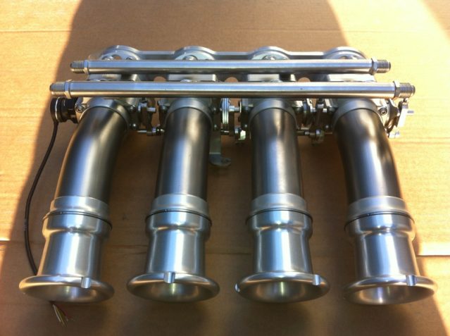
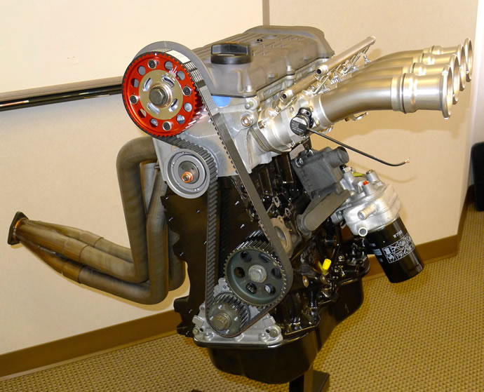
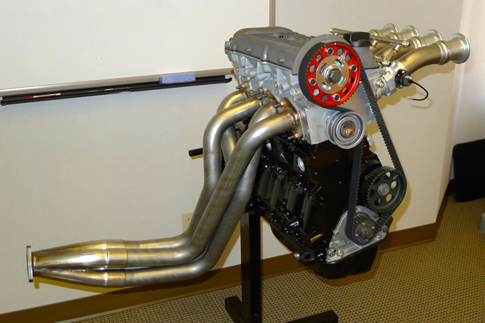
The AT Power Individual Throttle Body intake system for the 2092cc stroker VW 16V ABF/9A motor
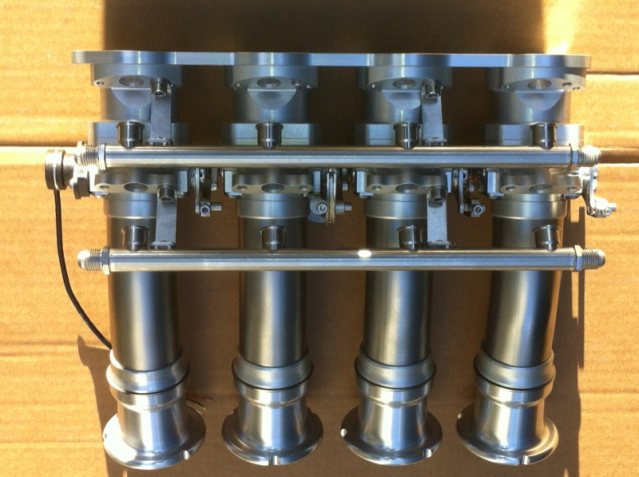
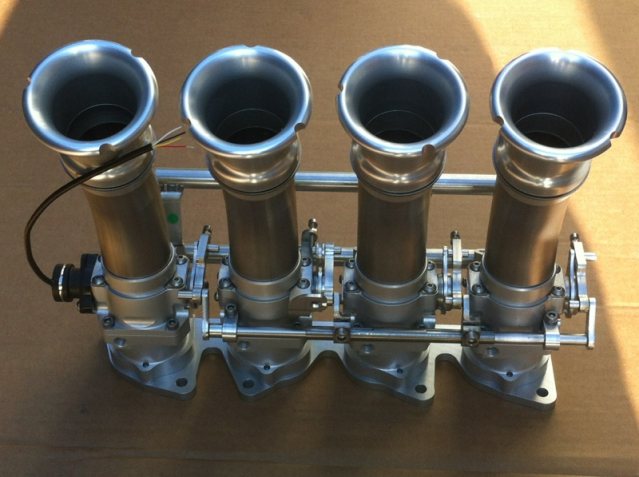
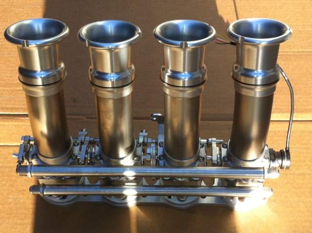
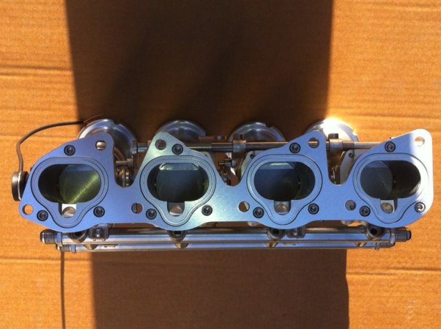
Photos taken March 12/13 2014 when the engine was completed:


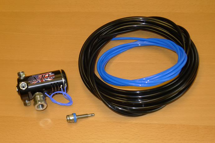
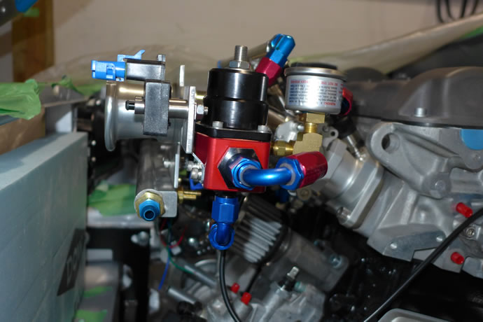
NOS Wizards Quadranoid, a dry flow nozzle, and small ID plastic tubing - May 9, 2014
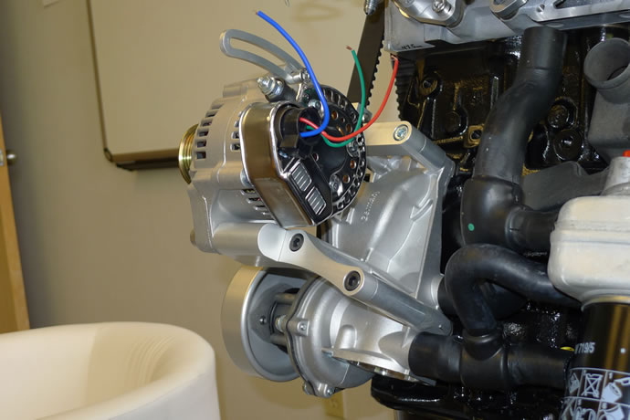
EAA Engineering's Serpentine Belt System, Fluidamper, and Denso Racing Alternator (all put together with clear anodized billet aluminum CNC mounts) - a must use system to clear the ITBs - May 9, 2014

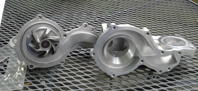
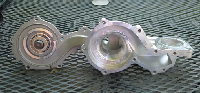
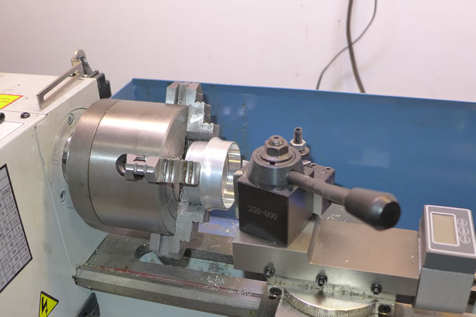
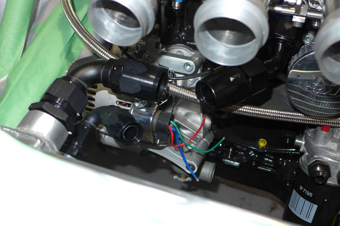
Now that I have ordered the Davies Craig electric water pump and digital controller it is time to prepare the OEM water pump by cutting off the impeller, aux water return ports (which will be tapped and plugged), and smoothing the interior for its new function as a passive entry way into the block from the outlet of the EWP - August 17, 2014
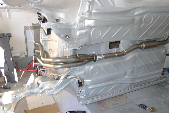
Rough positioning of the Techtonics stainless custom 1-3/4" headers and 2-1/4" exhaust system plumbing (note, we are keeping the pipe size at 2-1/4" because this is the size that TT says has proven to produce the most power in normally aspirated cars: 2-1/2" is only suitable for turbo engines) - September 8, 2014
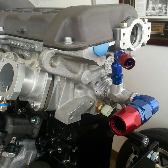
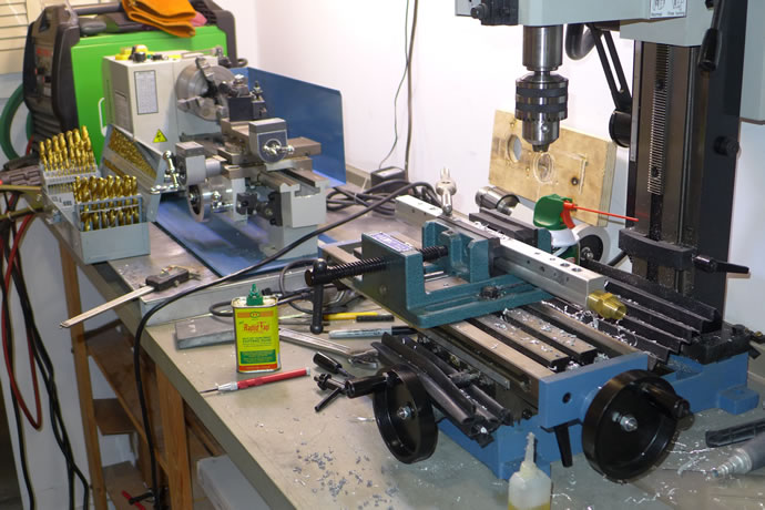
After a lot of machining and fiddling around I managed to complete the front cylinder head coolant outlet flange that is required to clear the ITBs and associated linkage, nitrous and vacuum lines, etc. - September 14, 2014

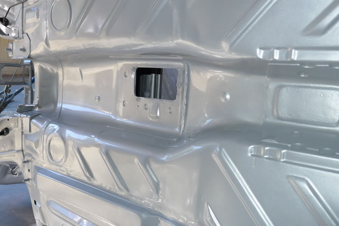
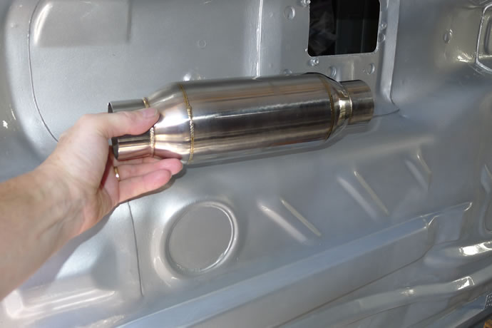
After speaking with Techtonics about the exhaust system clearance issues I cut off all of the tunnel flanges and bolts, filled, sanded, primed and painted it all so now there will be nothing hitting the pipes. I also sourced a really nice and small Vibrant stainless resonator that will be welded onto the back of the flex coupling: this way I will havee 2 resonators plus a muffler so that I can make 'quiet power' which is my goal - September 14, 2014
The shifter housing after cleaning it up and epoxy painting it - September 14, 2014
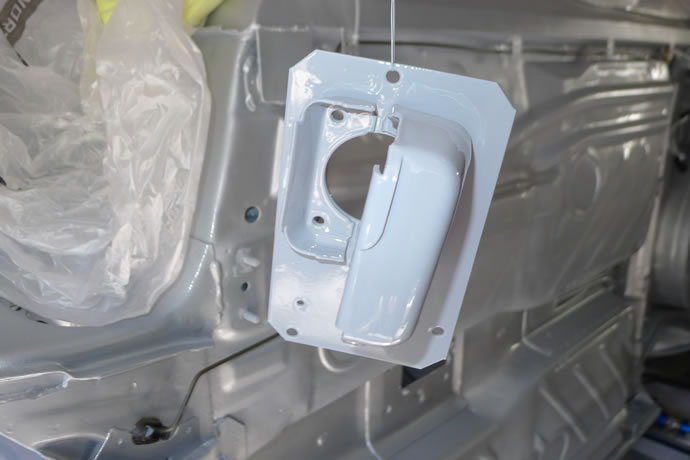
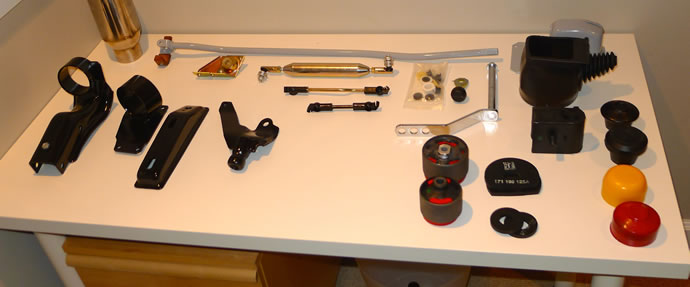
I have been busy using my Caswell Zinc/Copy Cad plating system to rescue all kinds of brackets and bolts since I have not been able to complete my brake lines until the MasterCool flaring tool arrives (ETA tomorrow). I plated the metal objects that were OEM plated and stopped there but for those parts that were originally painted black I first stripped them down, acid etched, plated and chromated them to provide an extra measure of protection before painting - September 23, 2014
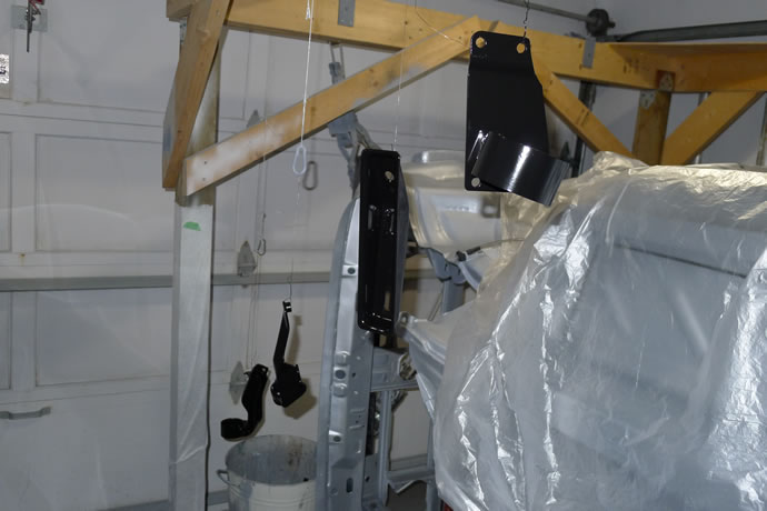
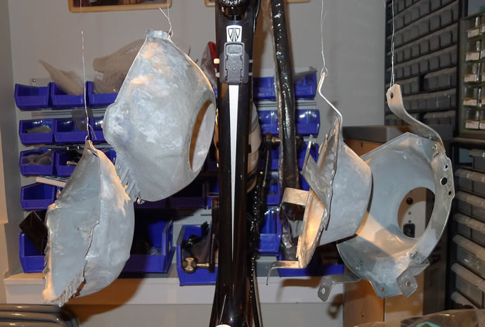
This has been a big week with lots of progress. Below are photos of the plating/painting of the headlight housings, the various motor mounts and inserts/shift linkage, etc going into the car, and the heat shielding. Not shown is the braking system which is now complete and the Quaife steering rack which is also now complete (see other web page) - September 28, 2014
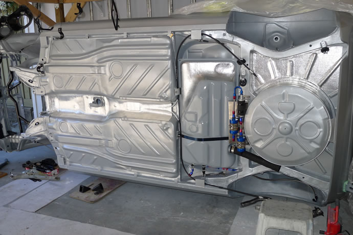
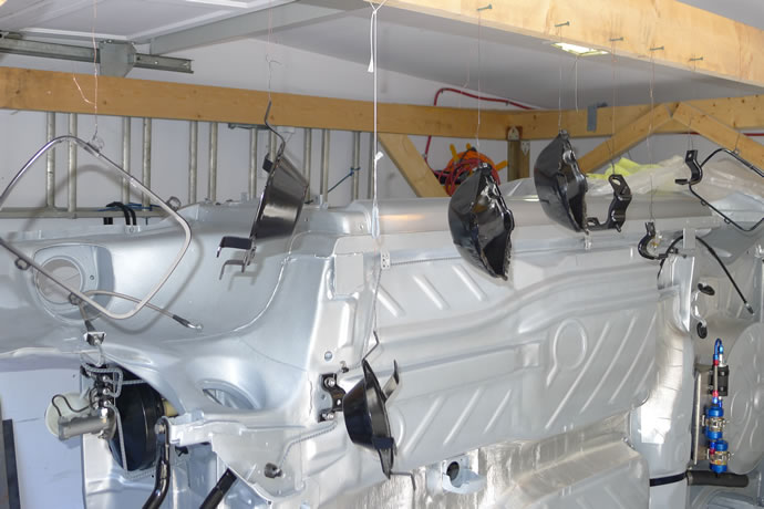
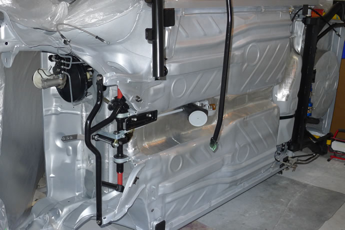
The rear end is complete and torqued to spec, the steering rack and shifter linkage is now mounted in the front and now I am getting ready to flip the chassis upright for the last time - October 6, 2014
... and the 020 2Y German Transaxle of America transmission with Quaife LSD is sitting here, waiting for the custom clutch/pressure plate which Josh says will ship to me later this week ...
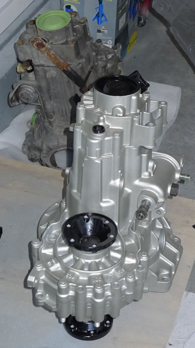
Quaife transmission differential ...
There is an excellent VW transmission specifications reference site at http://www.rabbitgtipage.com/transmission.html
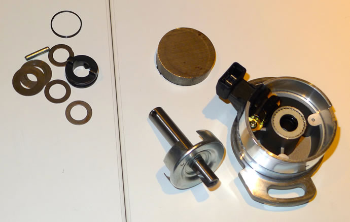
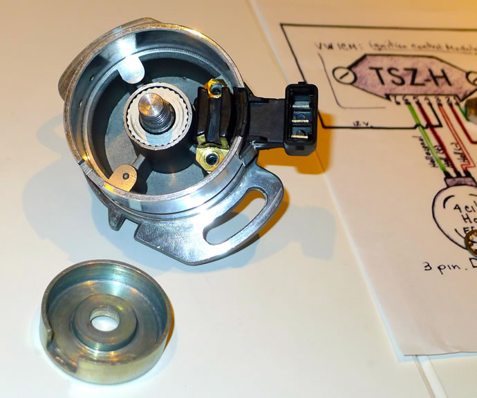
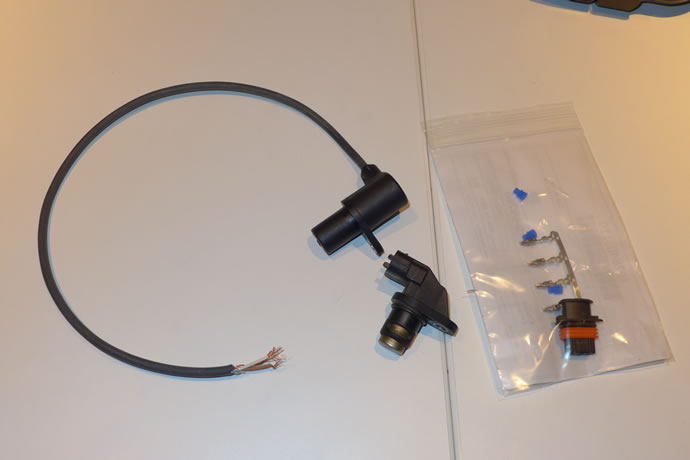
The engine is now getting very close to mating with the transmission, and installed into the chassis- hopefully this weekend. Below are some before and after photos of the cam position sensor, turning the OEM unit from a 4 position sensor to a simple TDC #! sensor - October 21, 2014
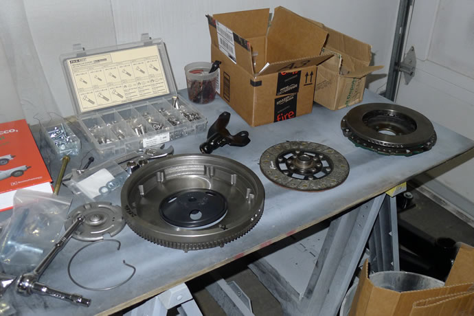
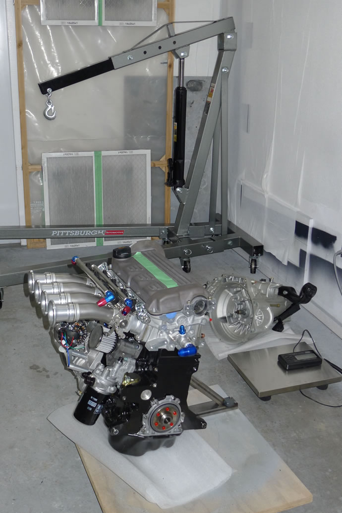
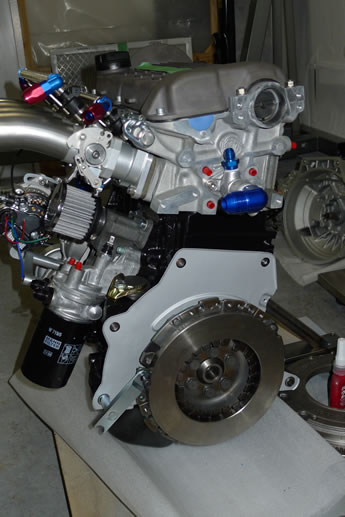
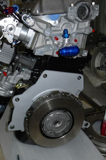
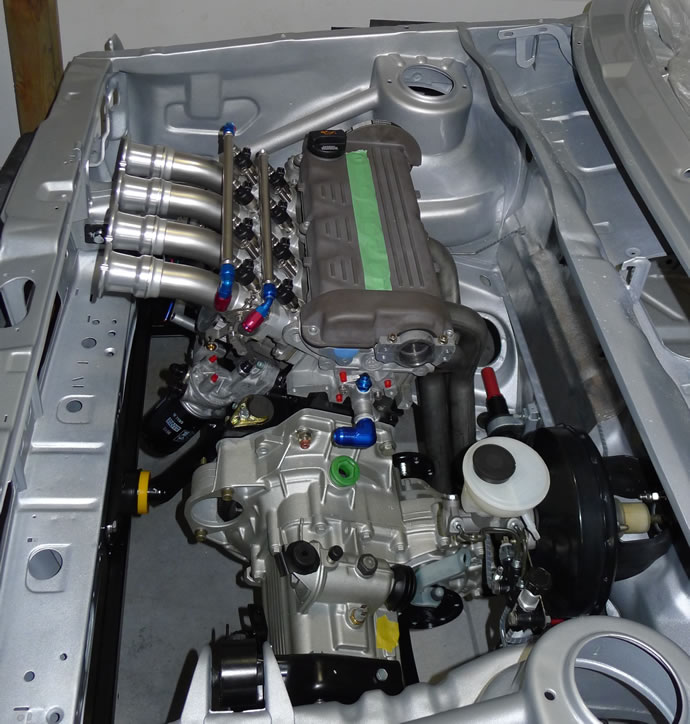
Major Project Milestone: Today was the big day - getting the clutch setup done, and then assembling the engine and transaxle, rolling it under the chassis and then hoisting it into place. Everything went well except for the fact that I had to remove the rear engine/trans mount to get the side mounts to line up first which is a lesson learned, and I also discovered to my dread that I will have to mandrel bend the intake runners another 20 degrees or so to clear the hood - October 25, 2014


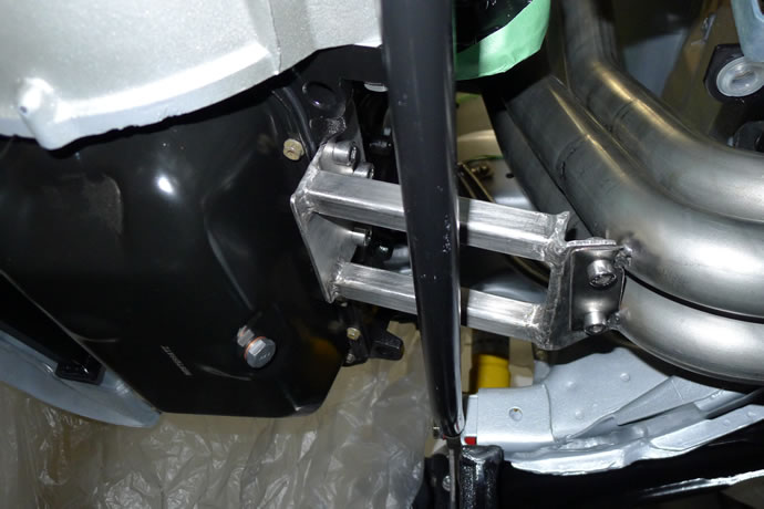
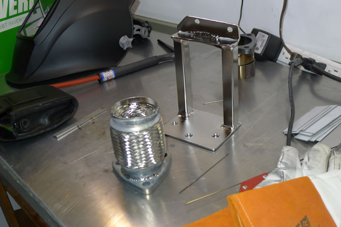
I am building a structural support brace for the race header that connects the lower end of the header back to the base of engine block to keep the stress levels on the flanges to a minimum - November 2, 2014
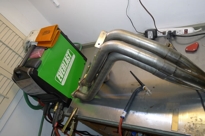
Here is the completed structural support brace for the race header, also a photo of it after electrocleaning, and the header itself after porting/polishing but before internal ceramic thermal barrier coating - November 11, 2014
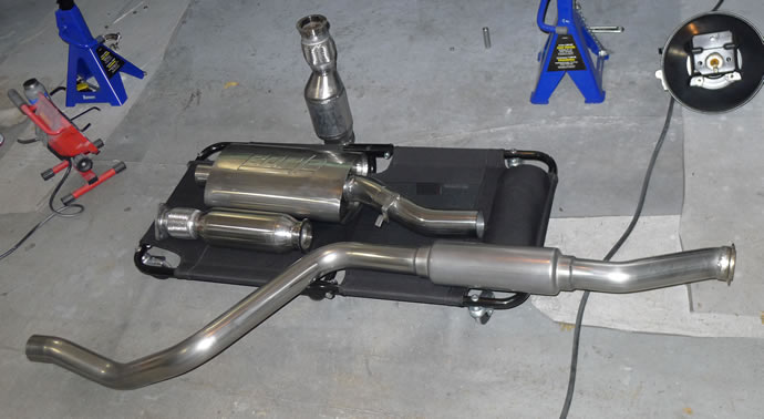
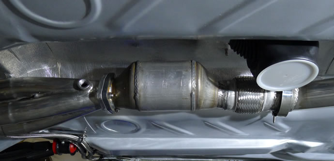
I completed the exhaust system this week. Below are photos of the V-band clamping system I have used to allow me to quickly swap the cat converter in/out in favour of a high performance resonator that will keep noise levels down to where I want them (a total of 3 'straight-thru' resonators make up the entire system), the welded up and polished components, and finally the 2.5" tip that says 'we mean business' - November 23, 2014

The 'optional' cat converter in place ... (I had to swap the flex pipe to the back end to clear the shifter boot)
The completed system with the 2.5" tailpipe ...
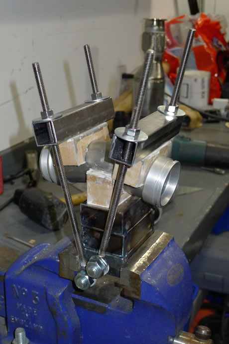
I have been noodling away on solving my problem of the ITB intake runners being too high (interference wit the hood). This problem was caused by not remembering that the ABA block is a lot taller than the earlier mk1 and mk2 blocks. In fact my second injector fuel rail is close to hitting the hood as well! Anyway, I sourced high strength molding epoxy and built cardboard molds in the shape of the runners, which are 45mm ID, 48mm OD. I then mounted the epoxy molds onto steel plates and used threaded rods to allow me to apply bending pressure to increase the bend another 10 degrees or so - but those steel tubes would not budge 1mm, even with 500lbs of force. Eventually the epoxy 'caps' that I had made up snapped.
The good news is that today I finally found 48mm OD, 1.5mm wall thickness T304 stainless tubing, mandrel bent at 30 degrees, from the UK, which puts the intakes in the right position to clear the hood. I am trying to get an order placed along with another order from AT Power for another set of inlet/outlet caps for their ITB assemblies so that I don't have the try and un-glue the current intake runners (I did one today and made a mess of it as the glue, even when heated to 500 degrees, holds very strongly).
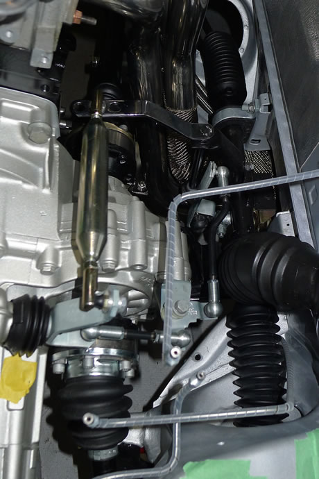
It looks like I should have this challenge behind me in a few more weeks. In the mean time I got the shifter linkage installed and all dialed in using the Techtonics shifter kit plus the 4crawler adjustable steel end links which allowed me to get the 1-2 gate positioned exactly where I wanted it (just to the right of the reverse lockout). I will get the brake system/pedal assembly done this weekend - December 9, 2014
Techtonics shifter kit plus 4crawler adjustable steel end-links (all dialed in) ...
I received my shipment from Any-Exhaust-Part of the UK for the 48mm T304 intake tubes today and so I could not resist cutting them up immediately and test fitting them to the throttle bodies. Success! I now have the right angle and length to avoid hitting the hood, leaving enough room for the radiator/shroud/fans and the proper geometry for an efficient cold air intake box. I will still have to wait for AT Power to ship me the new collars as it is a real bitch to unglue the ones on the existing intake runners (and then I have to machine the collar IDs about 1mm to fit the new tubes once they arrive) - December 17, 2014
With the new ITB intake runner collars now in my hands I was able to get the intake system completed: I previously sourced new 48mm stainless tubing that was pre-bent at a 30 degree angle, cut them to the right length, ordered new collars, machined them to match the tubing exactly, made up the back plate for the air intake box, glued the collars onto the runners, assembled quickly, aligned, and will let sit overnight to cure. Now I can start to fabricate the rest of the air intake box. No more interference with the hood! - January 18, 2015
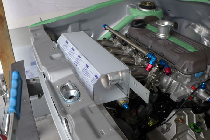
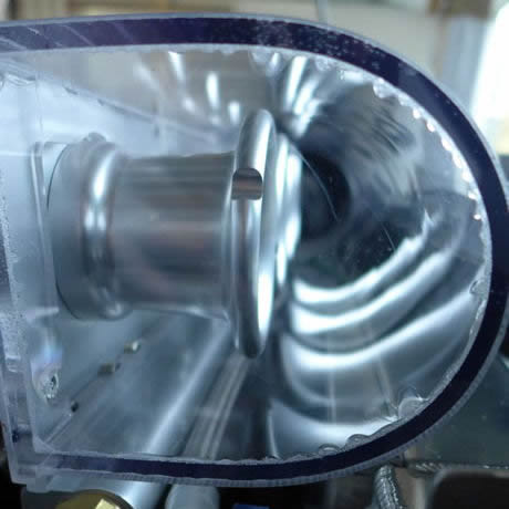
I made satisfying progress this week on the fabrication of the intake vacuum plenum, related sensor mounting, and all of the machining and tapping of the various connectors, including the nitrous solenoid. I was missing a 1/16 NPT tap in my tool chest and there was no supplier open today with the part I needed so I have ordered it from Amazon and will finish the tapping of the 4 ITB vacuum lines later this coming week. I also made an important decision to make the air box out of clear Lexan and put 2 of 2.75"x2.6"x12" K&N air filter elements (they provide 50 sq. inches of pleated filter element per unit) between the top of my custom radiator and the cross member, creating a Lexan funnel into the filters in front of the radiator, and then having a straight shot into the air box, rather than trying to create a long indirect 3 or 4" tube to pull in cold air from under the car (I am really excited about this new idea and think it will work out perfectly) - January 24, 2015
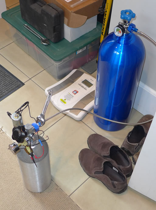
Over the past few days I managed to work on the cooling system after receiving some of the key parts - unfortunately, the Davies Craig electric water pump -20AN fittings weren't properly machined so I will not be able to finish this until new fittings are sourced. I also had another delay with the completion of the custom radiator - in fact we are starting over with a 1" narrower radiator core so that the side tanks are a full 2" wide to allow for the proper mounting of the -20 ORB fitting and other fittings. The new core will be in the hands of the fabricator Tuesday and with any luck I will have the completed rad in my hands in another week ... I also got the 1/16"NPT tap for the ITB vacuum lines so made more progress on the intake system, plus I got the K&N air filters, the speedo electronic speed sensor for the 020 trans, and a few other items. Finally, I ordered all of the components for the nitrous 'push' system which I will cover in a future video: it consists of a 4500psi air tank, a high pressure solenoid controlled by an adjustable pressure switch, and a normal nitrous tank: the pressure switch is set to 950psi and opens when-ever the nitrous pressure drops, allowing high pressure air to 'push' into the nitrous tank and keep a consistent pressure at all times, regardless of nitrous level or temperature. This is a much more involved system than a bottle warmer and obviously reacts instantly to keep the pressure constant as the nitrous is flowing ... stay tuned for more info - February 1, 2015


Fedex delivered my shiny new custom radiator from http://www.bsandbradiator.com/ today. A quick test fit confirmed a proper fit under the hood and so I was able to order all of the remaining hose end fittings and start to plan out the fabrication of some stainless brackets to support the water pump and coolant-to-oil intercooler. Tomorrow I will pick up a lot of goodies including the remaining air box components, nitrous system components, etc. - February 11, 2015
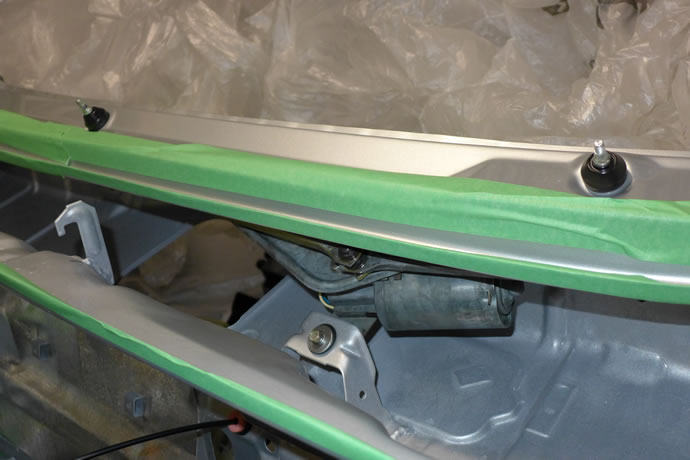
After a number weeks of business travel I managed to make some GTI project progress this weekend, first installing the re-built wiper motor assembly with new rubber grommets, and then test fitting some new coolant hose-ends in preparation for this week's task of putting together the remainder of the air intake system, fuel system and coolant system. I also got a chance to run some more air flow testing on the low profile SPAL radiator fans (yes, they flow a lot of air when mounted to the rad, more than enough) - March 8, 2015
This last week I got the custom radiator mounted properly, sorted out more of the coolant fittings, discovered a major interference issue with the -16 upper hose running into the vacuum plenum, built a number of Lexan air boxes (a few fails and then a successful one), and ended the weekend feeling pretty happy that things were coming together as (almost) planned. I also got my nitrous bottles filled and played around with the system a bit more: I will be doing PWM calibration testing on it this coming week - March 15, 2015
Rubber grommet mounts for the radiator ...

Ahhh, the carbon hood looks good ...
air box fail #2 (fail #1 was trying to heat and bend the Lexan sheets) ...
success on attempt #3 ...
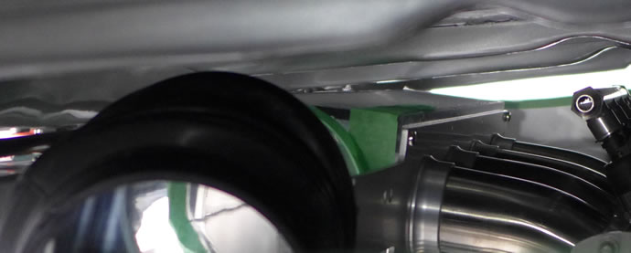
and the airbox doesn't look like it will hit the hood ...
Over the weekend I setup the nitrous system properly on the bench with the custom high pressure air 'push system' and ran a series of linearity tests while pulse width modulating the trick new Quadranoid solenoid (from NOS Wizards in the UK). I consumed 20lbs of nitrous doing all of the tests and learned a lot about the optimum settings for that solenoid. I don't want to run a lot of nitrous in my car as it could hurt my beautiful engine with its ultra precise tolerances (nitrous rapidly increases the combustion temperatures and in turn causes the pistons to expand, etc.). I only want a range of 15-60hp under computer control, not 100hp+.
When I initially installed the 20hp jets, instead of seeing 20/40/60/80hp at 25/50/75/100% duty cycle, I got a range of 80-110hp using a frequency of 35Hz. It turned out that while the Quadranoid is rated to 50Hz, it needs to have the plunger adjusted (a unique NOS Wizards feature) to a minimum height so the range of motion is dramatically reduced, and then it can be accurately controlled at high frequencies. With the seat height at the stock full open setting the plunger just floats when modulated at anything more than 15-20Hz and that is too low of a frequency for my application (intake valves open and close 60 times a second at 8000rpm). While 35Hz, which is the limit for my Holley Dominator ECU, is below the rate of intake valve opening at max rpm, I am feeding the modulated nitrous into a small chamber in the base of the Quadranoid, and then thru the distribution block/jets and then thru tubing to the intake runners: by the time the PWM controlled nitrous comes out the end of the tubes it is almost flowing smoothy - it has a slight pulsing to it but not a ton.
I found that even with the seat height set fairly low the Quadranoid still flowed a ton of nitrous so I switched to the 15hp jets and set the seat height even lower - almost off. And then I got the #s I was looking for: 15/30/45/60hp at 25/50/75/100% duty cycle. One thing I am really interested in is seeing if the 15hp setting will actually produce more like 25hp due to the cooling effect that nitrous has on the intake charge. Nitrous provides additional O2 but it also cools as it vaporizes so even really small amounts of nitrous can add significant power. I am not interested just in peak hp, I want to use the nitrous at the mid-range to tame the 288 degree cams and add back in some of the mid-range torque that is lost due to excessive cam duration ... - March 24, 2015
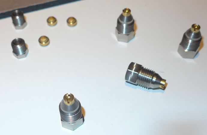
NOS Wizards uses a lot of BSPT and BSPP spec fittings plus they are religious about plastic piping (to keep the nitrous volume in the tubes low and the opportunity for vaporization down) so it is a bit of a pain to connect it to race spec AN fittings and such. One area that is really interesting is how they incorporate metering jets into their system: the brass jets screw into the 4mm plastic compression pipe fittings (on the insides no less) ...
Filling up my 5lbs nitrous bottle after chilling it in the freezer from the room temperature 20lbs supply tank ...
After realizing that the new custom radiator had a nasty interference fit between the upper -16 hose and the intake system vacuum plenum log I got busy and ordered up another -16 ORB bung, cut a hole at the bottom of the tank (too bad, it would have been better to have the hot coolant enter at the top) and got my buddy Danny Beaudry of Pro Gas Engineering to weld it in (I am not up to par on tricky aluminum TIG welding like this when it involves a combination of thick and thin materials plus when it has to be leak proof). I then mounted the radiator coolant recovery tank on the side of the fender and started to make up the coolant hoses (a job I will finish in the next week) ... - March 24, 2015
Cutting and welding in the new -16 ORB bung to solve the upper (no longer) rad hose interference fit ...
And then making a d installing the -12 and -16 hoses, plus building a mount for the rad coolant expansion tank ...

I got all of the cooland hoses complete, plus the remaining fuel system hoses, and the bracket fabricated to mount the coolant-oil intercooler - it turns out that there is no need to make up another electric water pump supporting bracket as the -20AN coupler to the radiator plus the -20AN short hose connection to the coolant-oil intercooler supports the EWP extremely well. I had trouble making up the -4AN vacuum lines that run between the vacuum plenum and each throttle body but I ended up ordering a Kool Tools stainless braided line funnel tool and cutting shears that should make the task of threading the cut hose into the hose ends for these really small -4AN hoses less of a torture session, complete with blood all over everything - April 5, 2015
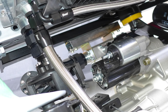
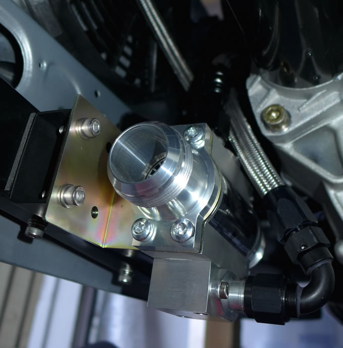
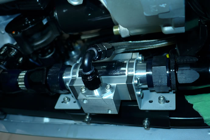
After Joey on YouTube suggested I try a banjo type hose end fitting for the oil line that connects to the bottom of the oil-to-coolant intercooler, I got to thinking that a banjo type fitting wouldn't likely flow as well as another similar idea: machining a block of aluminum to allow a right-angle mounting of the -8AN fitting off the side of the housing. I got to work today in my machine shop and now it is all together and the oil line is now slightly above the bottom lip of the chassis so I no longer risk hitting a critical oil line on a block of concrete or road hazard - April 13, 2015
The oil-to-coolant intercooler mounted up nicely with its new painted bracket, plus the oil lines were done and routed cleanly without rubbing against any painted surfaces (I did cutoff an unused bracket extension from the side of the starter motor to provide more clearance). With this job complete I have finished making all of the Stainless AN lines so I removed all of them from the engine and washed and blow-dried the lines so I can now install them permanently later this week when I will also install the heater core and air box inside the passenger compartment - April 20, 2015
After fighting with the old heater valve cable for about 2 hours (trying to lubricate it so that it would slide smoothly and open/close the heater valve) I gave up and found a replacement Gemo p/n 161819837 on ebay that looks like it will work fine in my mk1 application. I then fitted up the remaining cables that were in perfect working condition and mounted the heater/HVAC box in the chassis with its new gaskets. I was then able to hook up and complete the coolant system lines in the engine bay and pressure test the complete system to 15psi - success! I was also able to install many of the engine sensors and started to design a mounting bracket for the Holley Dominator ECU and ignition coils that will be placed in the rain tray on the passenger side (it is all weather proof but won't really see any water where it will be placed) - April 25, 2015
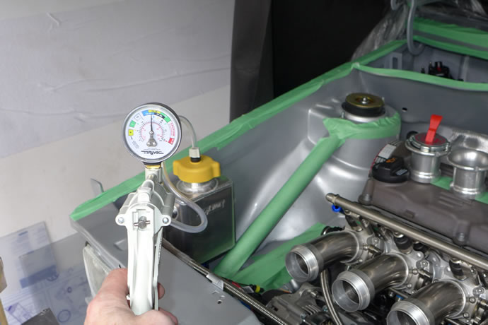
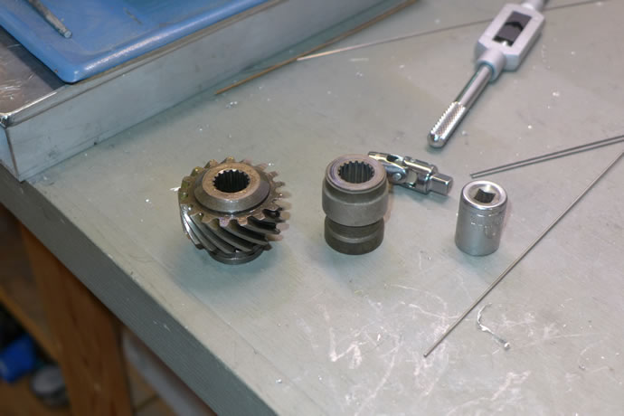
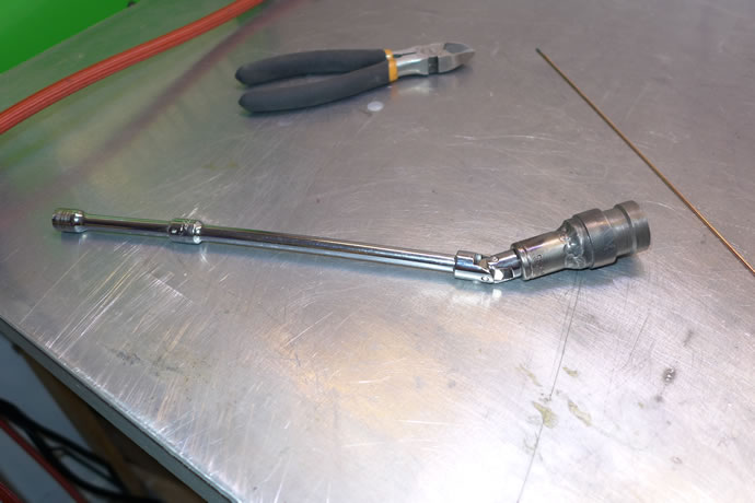
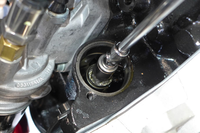
I managed to get the intake system 'final assembled' and get all of the fluids into the engine/trans: the coolant, and I tested the system with electrical water pump; the transmission fluid; the engine break-in oil, and I made up an oil pump drive tool to prime and test the system (using a VW p/n 027115027 oil pump drive gear from a 16V ABA motor, machining off the gears, and then TIG welding on a 1/4" socket); and finally the fuel in the tank and testing of the fuel system. And yes, there were lots of false starts, dripping fluids, and some new injector o-rings are now on order - May 19, 2015
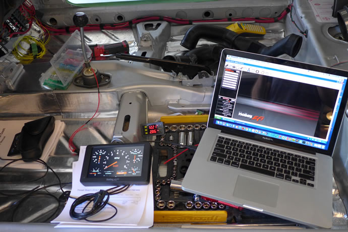
I had been fighting the computer and sensors for the past several days but finally have it running now. Boy, it starts with authority and has a serious exhaust note to it (not really loud at all at idle but when the throttle opens it gets serious in a hurry). With the 288 race cams it will idle roughly at 900rpm but prefers to be closer to 1050rpm for smooth idle. I was expected worse ... seems that the ITBs saved the day.
I had fabricated a hall effect sensor for the crank position 60-2 wheel from a late model mercedes but it turned out to not like the tooth width/depth and would give the computer erratic timing info at anything past 200-300 cranking rpm. I had to go back to the ABA inductive sensor (analog output) that the Holley dominator ECU accepted. Once that was out of the way I got correct timing for the ignition/firing of all plugs, and all other sensors were operational. But then it would fire and immediately die after transitioning from the cranking parameters to the running parameters. Turns out that Holley means zero fuel enrichment when programmed for 100% - I had it set to 'zero' and that means 'kill the fuel injectors'. Go figure. Anyway, I have lots of programming left to do as the AFR learning is limited to modifying the parameters a fixed % beyond the base tables, not learning all of the fuel tables from scratch. My tables aren't close enough yet to allow the engine to run beyond 2000 rpm without leaning out so I will be at it again tomorrow sorting out the tables. It starts nicely now, builds lots of oil pressure, the cooling system programming all seems to work nicely (the electric water pump speeds up and slows down as required, the cooling fans speed up and slow down as well, etc - all really trick/nice to see).
Boy a new engine smells a lot when it first heats up!
I used the brakes and put the trans into 2nd gear and got up to about 40-50% throttle on it up to a little under 5,000rpm to help quickly seat the piston rings and auto-learn the base fuel tables. All went well and now I am going to take a much needed break from the project for a few weeks and go on a family holiday and will then head into the fall with the idea of completing the car and getting it licensed and on the road ... - July 22, 2015
Tragedy has (almost) struck the ultimate GTI project. Cylinder #2 high mount 30lbs/hr injector failed (this never happens) in the ‘on’ position, filling the engine with fuel when I was doing ECU fuel table learning under load. Potentially serious issue as fuel is not compressible and could result in bent internals. Freak failure. Never seen or heard of this happening before. Not an electrical issue. Simply an injector that decided to die and let the fuel pour out of it. I took the intake system apart, cleaned up and got the fuel completely out, etc.
Did a compression test: 180psi on all 4 cylinders on a cold engine. This is actually a great result given the 288 solid lifter cam with its large valve overlap specs. Will have a new injector tomorrow. Will change the oil and should be back in the game this weekend - August 6, 2015
After sourcing a new injector, cleaning up the mess from dumping so much fuel into the engine, lubricating the cylinders with Sea-foam cleaner/lube, cleaning and re-installing the O2 sensor and Denso spark plugs, and bolting everything back together there were no more fuel leaks or sticking injector issues.
I put more time into re-scaling the fuel and ignition tables, expanding the area from 70-102kPa MAP where the engine operates with the 288 race cams, tuning the idle IAC parameters, and also tuning the timing around idle and low-rpm part throttle, enabling idle stabilization via timing variation, programming in the acceleration enrichment tables, and otherwise leaning out the fuel table parameters to compensate for the low volumetric efficiency below 5000rpm, and after all of that the engine starts nicely, settles into idle smoothly, and has a very crisp throttle response, which is to be expected of an ITB setup.
Now that this is all done and a lot of the basic A/F ratio fuel table tuning has been done/learning completed, I won't fire the engine again until the wheels are on the ground and the rest of the interior and wiring is basically completed. It has 180psi cold compression on all 4 cylinders and is broken-in enough for me not to worry about idling it.
Now a few comments on the design decisions re. cam selection and other related engine components: We put these cams in at the last minute after previously deciding to build a set of race-ready heads and intake system with mild cams (a combination that pretty much achieves the best of both worlds) and then Josh (the engine builder) and I mused about first seeing what the potential of this engine was with the 288 cams, and then, if it was too much for the street we would swap in 276 or milder cams later on. I will likely also swap in softer sport H&R springs and have Bilstein re-valve the race struts for the same reason: first to demonstrate the full performance envelope of the project car and then bring it down to earth a bit with some de-tuning.
There is a birdie whispering in my ear saying that the 288 cams might actually be streetable simply because the ITBs allow for fairly smooth idle even with very low vacuum and the car is so light relative to the power output (likely 1800lbs and 250hp w/o nitrous) so the lack of low end torque may not be an issue - and it may help soften the throttle response at low rpms that otherwise might be over-the-top with the ITBs. I also have the option of having the nitrous come on below the torque peak at 2500-5000rpm to compensate and then shut off. We have used this trick with big turbo setups to spin up the turbos and cut lag by 70% or more and then shut off the nitrous. The ITBs are a related issue as the throttle response of this setup at low rpm is tremendous and I can only imagine how crisp and aggressive it will feel above 5500rpm when the cams are in their sweet spot. I like a crisp throttle but the problem I have with this engine is that the ITBs are huge (45mm but shaftless so equivalent to 48mm units) so essentially one throttle body can supply all of the engine air needs on its own and when those 4 blades all open together only a few % there is a dramatic increase in air flow. It reminds me of how my old 83 GTI felt when I swapped in a Weber 'Big Throat' TB - it got tiring after a while with the overly sensitive throttle - and that was with a 100hp/2100lbs car. I can only imagine how much more sensitive this project car's throttle response will be and how tiring it may be to have to be so careful with my right foot all of the time. We'll see soon enough ... fingers crossed.
Something else I was worried about was how the exhaust note would sound. I have used multiple race-type resonators stacked end-to-end in street/track cars in the past with great success (quiet yet no loss of top end power - actually building mid-range torque over less muffled exhaust systems) so I used 3 straight-thru resonators on this project car. I will have to get one of my studio big diaphragm mics out and record the sounds for everyone to hear properly. The exhaust is quite mellow with a deep bass but not a lot of high end - which is what I expected to hear. When the throttle is opened up it is quite aggressive sounding but not like the usual rice-rockets on the road these days. I think it will be perfect but I need to get the car out of the garage to hear it properly - August 9, 2015
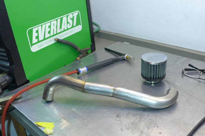
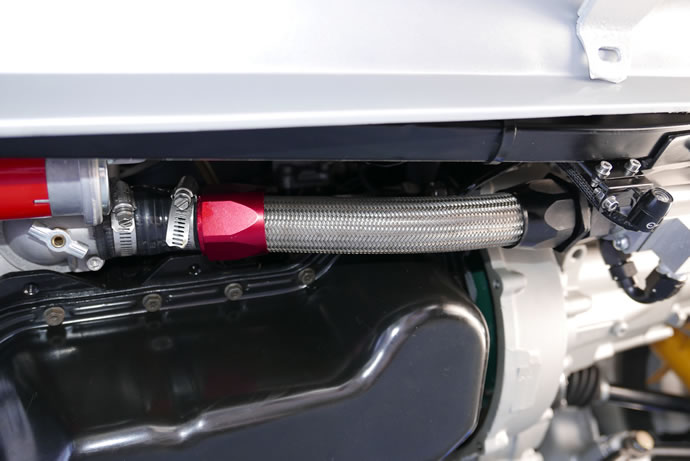
A problem I had when testing the engine was that I had mounted a small K&N crankcase breather filter on the end of the plastic OEM breather vent on the front of the ABA block which was not adequate to keep oil from splashing into the filter and then dripping all over the engine and garage floor. The not-so-simple solution was to design a 1.25" stainless steel vent tube that winds its way around all of the obstacles at the front of the engine to the side where the K&N filter can sit vertically above the engine block - with a slope in the vent tube that allows the oil that gets into the tube to drain back into the block - October 9, 2015

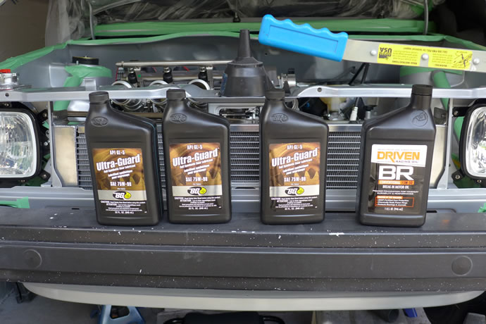
BTW, here is a comparison of the break-in engine oil pre/post the first 30 minute break-in period. No metal observed, no milky looks, just dark coloured, which I am assuming is mainly caused by the break-in lube used by my engine builder, Josh. I have asked him about this - October 21, 2015

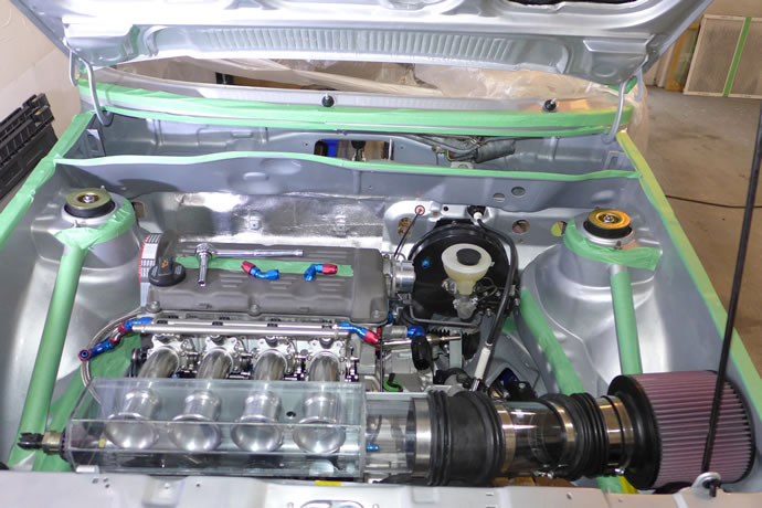
The speaker grills for the door cards were completed successfully, the audio system components are all now together and ready to be installed, the remote mounted Lithium battery was installed and tested with updated battery cables, the final A/C system components arrived and are now ready to be put together and tested out, and most importantly, I got a new Lexan curved cold air intake box made up and tested that looks great under the hood ... - November 5, 2015
I was hunting down the few remaining fluid leaks and so it was time to investigate why my Mocal Laminova oil to coolant intercooler was leaking oil. I contacted the SEM Laminova engineering firm in Sweden that makes the unit under contract for Mocal and they said 'Where did you get those brackets? They aren't from us and they are mounted incorrectly. The brackets must be positioned outside of the flanges, not on the inside.' Well, Mocal supplied the brackets but they did not fit on the outside as the ID was too small so I assumed that they needed to be sandwiched in-between the flanges and the body. Wrong assumption. So I machined them to fit, and put everything back together, put coolant and oil back into the system, and, fingers crossed, that will solve that leak. So far, so good. - December 25, 2015

The Davies Craig electric water pump controller uses a thermistor that they recommend be installed in the return line to the engine block. Wrong move. This resulted in wildly fluctuating cylinder head temperatures as my radiator does an excellent job of cooling the hot fluid before the thermistor reads it so I ripped up the nasty coolant return line plumbing and replaced everything with a clean -20AN stainless line from the oil cooler to the block and then machined the coolant flange on the side of the cylinder head to accept the thermistor - now the cylinder head temperature is stable at 190F +/- 2 degrees at all times and my oil temperature is also lower - September 22, 2016
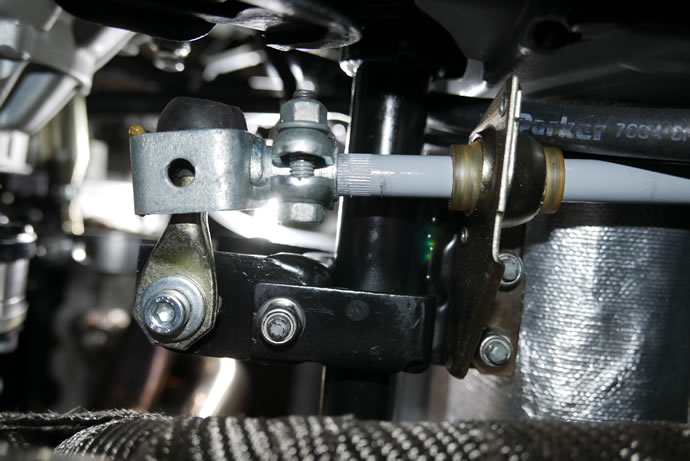
I had been struggling with poor shifter feel/engagement into 1st gear and so I set about disassembling the shift linkage in order to step-by-step find out where the problem area was. The transmission selector lever itself had a nice positive feel and clean engagement of each gear but I found that something in the linkage was resisting full movement into the 1/3/5 gear positions. It turned out that the rubber ball lever end wasn't moving smoothly and upon closer inspection I could see that the metal rod portion of the rubber ball lever was binding on the metal bracket that it is inserted into - and this was caused by the shifter rod being at the wrong angle as it entered the positioning bushing/bracket. So I pulled the shifter rod out of the car and bent it about 7 degrees about 8" back from the end and it was then perfectly parallel to the black mounting bracket assembly and positioned the metal bracket right in the middle of the rubber lever arm. I was worried that my 0.040" metal shim inside the metal bracket was causing binding with the rubber ball but once everything was aligned properly and greased up, the rubber ball rotated smoothly and didn't bind at all. With a 1/2" lengthening of the upper ball-joint arms to re-align with the new setup, everything was tested and then re-torqued into place. The result is 100% improved shifter feel and perfectly positive engagement in every gear. I am in shifter heaven now)- March 21, 2017
The shift rod before it was bent to be parallel to the black bracket assembly - you can see that the rubber ball isn't centered - causing binding and travel limiting of the 1/3/5 gear positions ...
I got my shifter extension built and love it ...
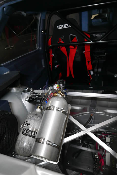
I fabricated an aluminum 'X' brace for the rear of the car which holds everything in position for road racing and also works nicely as an angled mount for the nitrous and air bottles - it still needs to be painted though - May 9, 2017


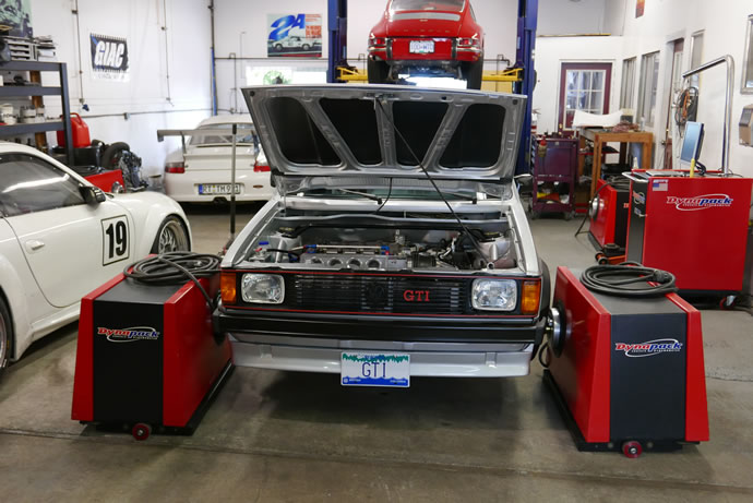
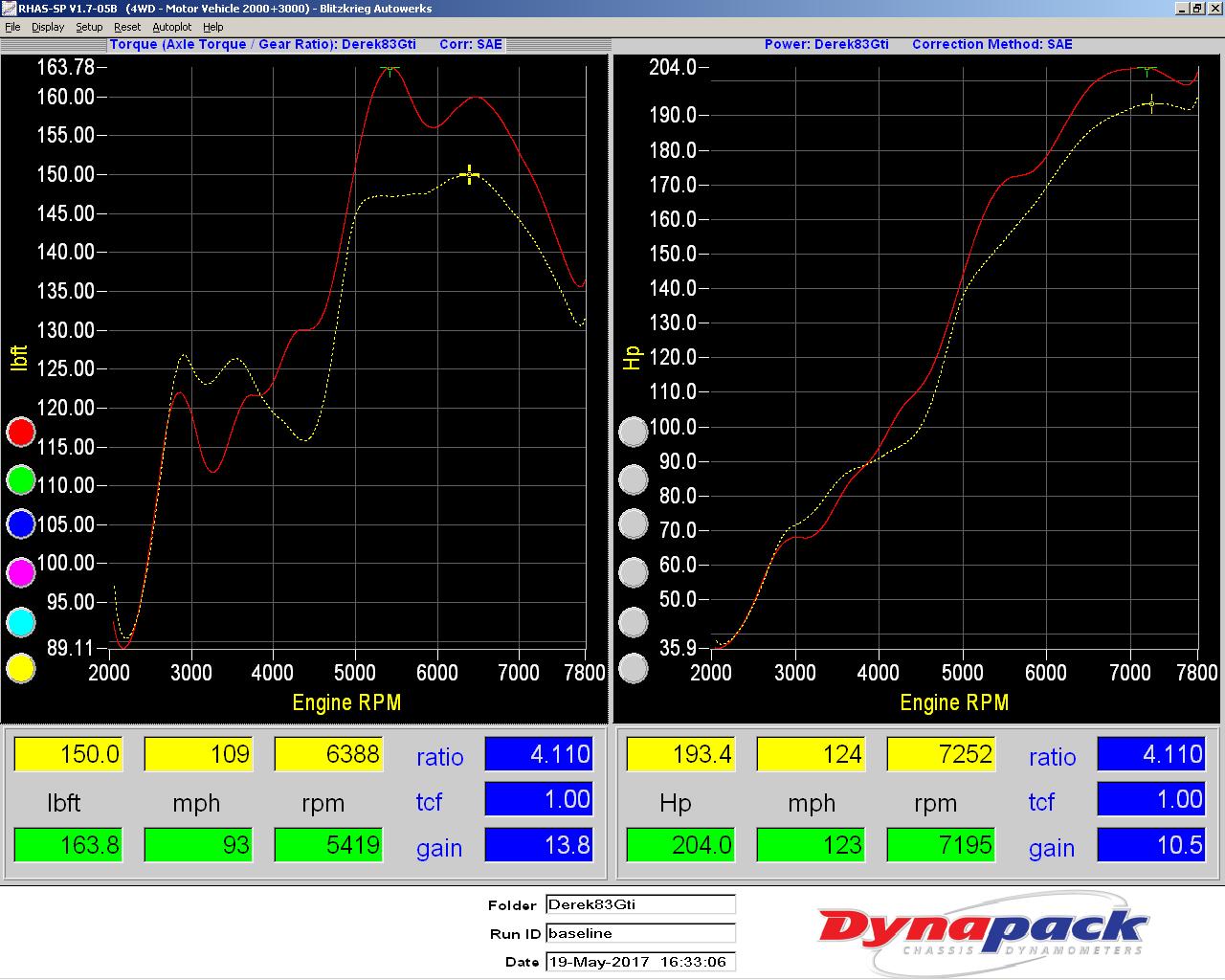
I spent a few hours at Blitzkrieg Automotive in Vancouver today with the GTI axle-bolted to their Dynapack dyno today and it was really a fun and worthwhile experience. The traditional roller-type chassis dynos have some potential variables with rolling friction that can vary depending on how tightly the car is held down onto the rollers while the Dynapack unit not only removes this variable (and any tire slip) but also securely holds the car in place without risks. The units are super expensive ($150,000) but their accuracy and repeatability are 1st rate. I was able to look for 1 and 2hp improvements over a range of parameters and slowly find missing power. We did about a dozen pulls covering fuel/air ratios, timing, injector end angle (the point in time when the injectors stop firing relative to the compression stroke), removal of the air box and filter and replacing the long intake trumpets with shorter trumpets. We were also going to test the nitrous system but the nitrous ECU enable line wasn't triggering the system properly so I will have to do this at the track and on the road next week (I found the problem later - Holley has a naming convention bug with the nitrous enable input that I had to work around by creating a touch-screen 'master nitrous enable' and then a ''stage 1 enable' using my dash mounted switch - I am pretty sure it will work now). Here are the test results:
191 hp @ 7200 rpm, 150 ft-lbs @ 6100 rpm - 13.0:1 A/F ratio, 26 degrees of total timing
192 hp / 151 ft-lbs - 13.2:1 A/F
194 hp / 151 ft-lbs - 13.4:1 A/F (13.6 saw a drop in power so this is the ideal A/F)
196 hp / 150 ft-lbs - 28 degrees of timing
197 hp / 150 ft-lbs - 30 degrees of timing
198hp / 150 ft-lbs - 32 degrees of timing (I did not attempt to advance the timing any further)
198hp @ 7200 rpm, / 162 ft-lbs @ 5400 rpm - no air box or filter
204 hp @ 7200 rpm / 164 ft-lbs @ 5400rpm - shorter intake runners/trumpets
Leaving the injector end angle at 0 degrees (start of compression stroke) was the default ECU setting and made the most power.
The big story was the removal of the air box and air filter - it increased the engine torque dramatically over a wide area from 5000-7000rpm and moved the torque peak down 1000 rpm - this will improve the overall acceleration 'area under the curve'. On the street it isn't practical to run unfiltered air into the engine (it will ruin it over the long haul) plus the noise from the ITBs is massive - you can hear the engine accelerating 10 blocks away with the air box removed - it is much louder than the exhaust system.
Dynapack dynos are reliable and conservative power measuring devices - to calculate crankshaft power add back the estimated 15% loss which brings this engine to 240hp which agrees exactly with my accelerometer testing last month so I will simply use my accelerometer testing for the nitrous system benchmarking next week. FYI, my 2L GTI engine produced the most power these guys have ever measured on this dyno of this size and type of motor - no other 2L 16V NA engine has exceeded 200hp before so they told me I have a 'sick' motor ... - May 19, 2017

Plots comparing pull #2 vs the final pull with all of the improvements in ECU programming complete ...

click here for a full-size image
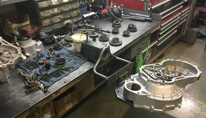
I have been taking people out for rides and part of the fun is doing some full throttle acceleration runs to show off the brutal acceleration potential of this car - when the cams hit their sweet spot between 5000 and 8000rpm things get more than just a little crazy with this 1900lbs FWD short wheel base car. But as I progressively did more acceleration runs I noticed that the transmission was getting harder to shift and there were strange noises coming from it when feathering the throttle - like marbles rolling around inside it or growling. So I drained the trans fluid and saw lots of silver flecks in the oil - a bad sign. I then spoke with Brian of Broke VW fame who has been so helpful to so many people in the VW 020 transmission world, who got me my 5th gear conversion setup and he suggested that it was indeed time to rebuild the transmission.
I called Ken Harvey at German Transaxle of America (in beautiful Bend, OR) where I originally sourced this 020 2Y (16V mk2) transmission from, and he said 'yes, I can rebuild it but I am leaving for vacation at the end of this week - when can you get it here?' so I ran into the garage and spent the next 3 hours pulling the transmission out of the car, throwing it into the back of my Audi A3 Etron and driving thru the night to get to Bend, OR by 8am the next morning. Ken gave me a wonderful tour of GTA which is definitely THE BEST VW transmission shop in America with its huge hard to find parts inventory and extensive rebuilding and testing capabilities. Ken got his team to work tearing it down immediately, getting the parts into the washer, repainting the case, and then completing an inspection of all of the internals. He found a badly damaged ring and pinion gear set and lots of worn synchros plus some worn bearings so all bearings and synchros were replaced, new R&P gearset installed, and some other items as well. It is now on its way back to me via UPS 2nd day air so I can get it re-installed in the car next week and then hopefully get on my way to San Francisco mid month - weather depending.
The bottom line in all of this is that I was using a transmission that was designed for 100ft-lbs of torque and running 200-250ft-lbs thru it at 50% higher rpm than spec on the race track, at the 1/4 mile strip, with slicks, power shifting, etc. - it lasted 4000kms which is actually quite good all considering. From now on it will be babied at lot more ... - June 27, 2019
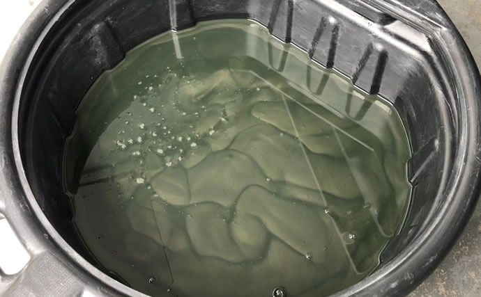
Silver flecks in the trans fluid - oh no!
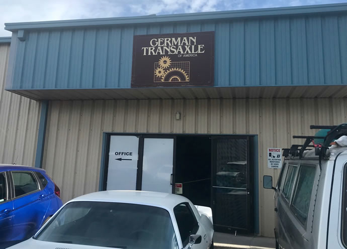

Arriving at GTA (German Transaxle of America) at 8am the next morning after driving thru the night and getting a tour from Ken Harvey who is the master of all things VW 020, plus many of the other VW gearboxes ...
The transmission after stripping it down and cleaning the parts ...

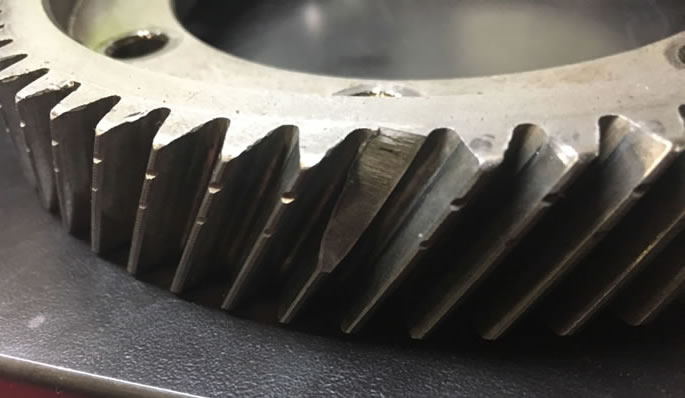
Holy crap - I am so lucky that the metal from those R&P gears didn't end up eating the whole transmission ...
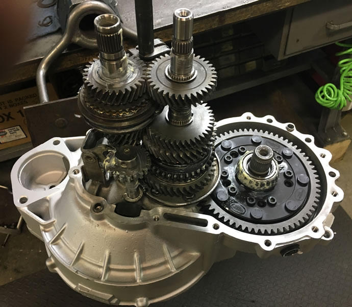
Coming back together with many new/replacement parts ...
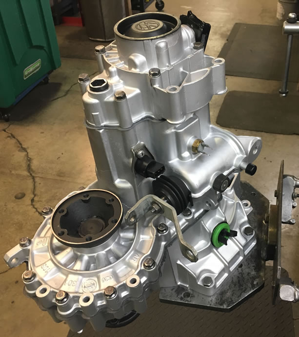
Finished in record time!
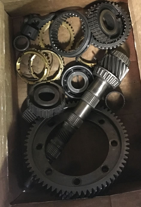
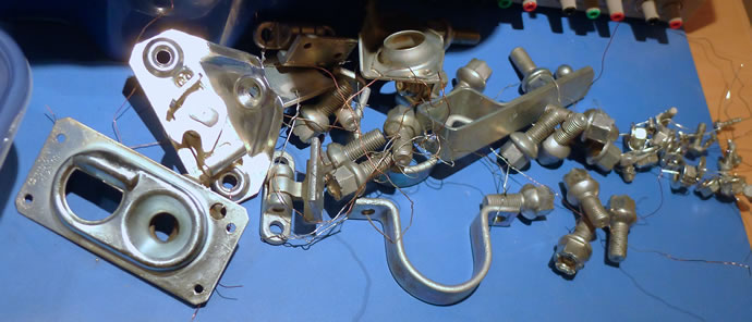
All the parts that were replaced ...
I used my ECU self-tuned fuel table to calculate the torque and HP curves for both my non-Cat and Cat equipped exhaust systems. Previously I had performed multiple dyno tests on the engine, determining that the best results were obtained without the intake ITB air box or filter, 32 degrees of total timing and a 13.2:1 air/fuel ratio, achieving 205hp at the wheels, which translates to around 240-250hp at the crankshaft. Adding the air box and filter cut about 10hp due to impairment of the ITB trumpet air flow characteristics.
I used 0.42lbs/hp-hr BSFC (brake specific fuel consumption) which agrees with my dyno test results and is inline with what race-prepped normally aspirated engines would see, vs 0.47-0.50 for a garden variety OEM engine.
The results were that the non-cat engine with the air box and filter registered 235hp and 180ft-lbs while the cat-equipped engine registered 218hp and 160ft-lbs of torque, but the real story is in the shape of the torque curves: the cat-equipped engine produces up to 40% more torque below 2000rpm and 11% more on average below 4500rpm where the majority of street driving occurs and only loses 7% on average above 4500rpm, and it has the effect of flattening out the torque curve so that it is almost level from 2500-7500rpm - making the engine feel very smooth and willing to rev over its complete rpm range.
On the track it makes sense to remove the air box and the cat and let the engine rip, but on the street it is far more enjoyable to have a car that is relatively quiet, smooth and tractable at all revs - without a fuel-rich smelly exhaust! I am very happy with the results.
As a background matter, running a cat with 288 race cams required leaning out the idle somewhat as well as backing off the timing at idle, plus reprogramming the fuel map to kill all fuel during deceleration - August 3, 2019

Index of Project web pages:
Project Overview, Goals & Specs
Project Car Initial Condition
Chassis Development
Bodywork & Paint
Suspension, Steering & Braking Systems
Engine, Oiling, Cooling, Transmission & Exhaust Systems
Electrical, A/C & Fuel Systems
Interior
Performance Validation
Final Street Trim Conversion
VW Vortex thread on this project
Videos # 001 - 049 (Feb 2013 - May 2014)
Videos # 050 - 099 (Jul 2014 - Sept 2015)
Videos # 100 - 149 (Sept 2015 - May 2017)
Videos # 150 - 181 (May 2017 - Dec 2019)
My original 1983 Rabbit GTI (owned 1983-1987)