
Project Ultimate 83 GTI
Electrical, Audio, A/C & Fuel Systems ...
Electrical System
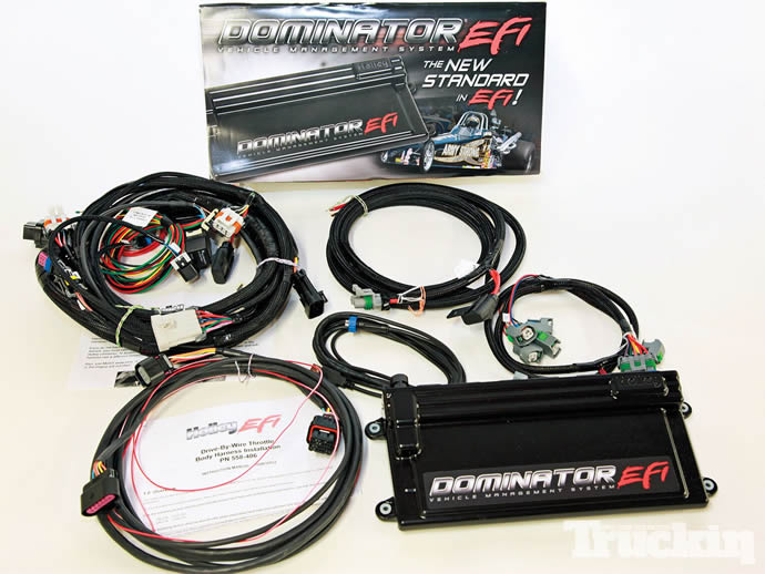
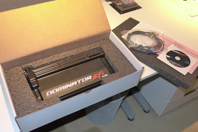
For the engine management system I chose what I beleive to be the most advanced ECU available in the market today: the Holly Dominator EFI system. It is a self-learning/mapping system that senses all fuel to air ratios via a wideband O2 sensor - this is a really powerful and unique feature. The Holley Dominator electronic computing unit (ECU) and digital dash is the heart of the GTI, monitoring and controlling a vast array of parameters throughout the car.
Holley ECU related software and product descriptions: https://www.holley.com/products/fuel_systems/fuel_injection/dominator_efi/dominator_ecu/parts/554-114
Here is a partial list of features:
- 12 sequentially driven injector drivers, capable of driving up to 24 low or high impedance injectors. Multiple staged injector strategies
- 12 channel Distributorless Ignition (DIS) outputs capable of directly driving “Smart” ignition coils or Holley DIS coils
- Integrated dual channel wide band oxygen sensor controls
- Integrated water/methanol injection control
- Integrated “Data Acquisition and Control”
- Self-tuning fuel table strategy greatly simplifies tuning process
- Advanced idle, closed loop, and enrichment strategies allow for very stable operation
- Two channel knock control sensor inputs for both one or two wire knock sensors
- Dedicated fuel and oil pressure inputs
- Controls both stepper and PWM Idle Air Control (IAC) motors
- Speed density, Alpha-N, or combination fueling strategies
- 3 Rev Limiters
- 30 - “Multi-Inputs” – Can be configured as a 0-5V sensor input, 0-20v sensor input, thermistor temperature input, or high or low voltage input
- 30 - 0-5V Sensor Inputs – Configures any 0-5V sensor as well as some can be used as switched high or low inputs
- 4 Stage nitrous oxide control
- Can be configured “Wet” or “Dry” with closed loop feedback
- Progressive control based on time, RPM, or boost, requires part # 554-111
- Lean or rich safety cutoff
- Full timing retard/control configurability per stage based on RPM or time
- Integrated water/methanol injection control
My ECU Global Config files: www.derekspratt.com/Misc/GTI_Holley_Global_Files.zip
GTI Engine inputs
Manifold Absolute Pressure (MAP)
Barometric Pressure
Air Inlet Temperature
Cam Position
Crank Position
Throttle Position
Knock Sensor
Fuel Pressure
Oil Temperature
Oil Pressure
Coolant Temperature – cylinder head
Coolant Temperature – radiator outlet
Transmission Speed
Fuel Tank Level
Nitrous Enable Switch
GTI Misc inputs
25AH LiFePO4 Battery Voltage & Current
Electric Water Pump Status
Acceleration/Braking Gs
Cornering Gs
Headlight Switch
Hi-Beams Switch
Turn Signals Switch x2
Kill Switch
Horn Switch
Parking Brake Switch
Seat Heater Temp Setting x2
Brake Servo Vacuum
Brake Pressure Setting
Blower Speed Setting
Audio Amplifier Temperature
A/C Enable Switch
A/C Compressor Speed
Cabin Air Temperature
Outside Air Temperature
Evaporator Air Outlet Temperature
A/C Compressor Temperature
A/C TXV R134a output Temperature
A/C Condenser R134a output Temperature
A/C Evaporator R134a output Temperature
GTI Engine Outputs
Fuel Pump Power
Nitrous Bottle Heater Power
Nitrous PWM Solenoid
Nitrous Purge Solenoid
Fuel Injectors x8
Radiator Fans PWM x2
Alarm Speaker
GTI Misc Outputs
Horn
Blower PWM
Seat Heaters PWM x2
Turn Signals x2
Emergency Flasher
Headlights On
Hi-Beams
Parking Lights
Brake vacuum pump x4
Audio Amplifier Fan PWM
A/C Compressor Fan PWM
A/C Condenser Fans PWM
A/C Compressor Power
A/C Compressor Speed x4
Alternator Voltage Control
Programming the Holley ECU’s dozens of screens and hundreds of parameters was an exhausting and time consuming process but in the end all systems work pretty much flawlessly with the engine starting cold or hot, idling nicely and having very good drivability manners. The ECU controls almost all aspects of the car’s functions, as can be inferred from the list of almost 100 inputs and outputs, and the digital touch screen dash is very customizable, with multiple screens available as desired. Plugging in a PC allows for quick updating and data logs analysis. Data logging of all parameters at 30 samples/second means that literally any transient condition can be captured accurately for later analysis.
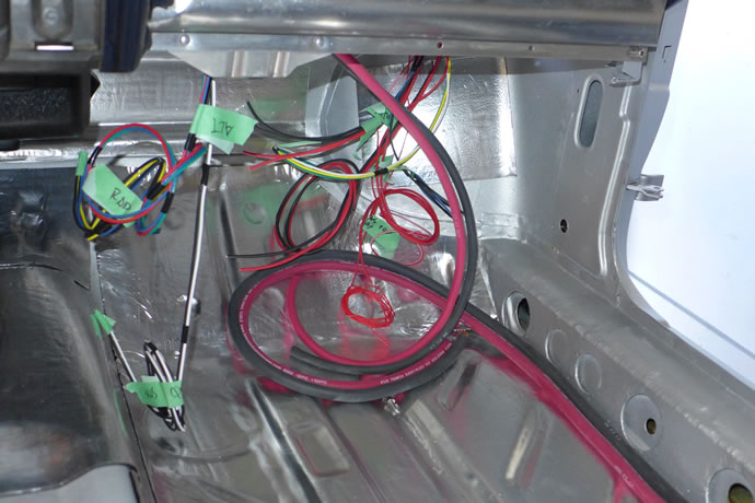
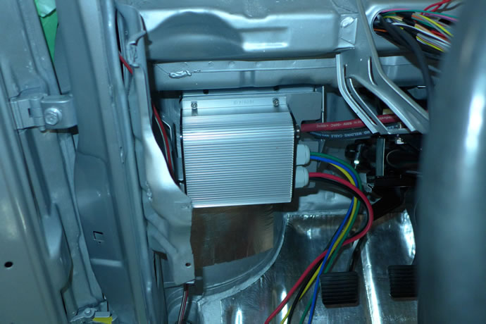
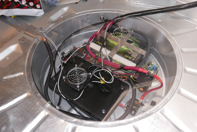
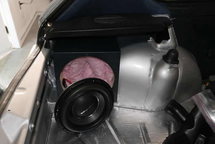
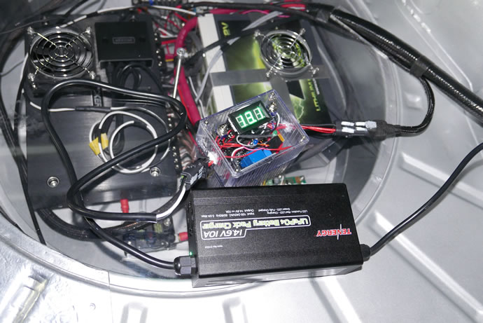
One of the key aspects of the electrical system is the LiFePO4 25amp-hour Lithium battery which only weighs 7lbs but has the power and reliability to outperform a 40lbs lead-acid battery. It is placed in the rear wheel-well alongside the current monitoring and battery wireless disconnect circuits, as well as the 1200W 5 channel audio amplifier and Bluetooth module. While a lithium battery provides much less voltage drop when cranking the engine than a lead-acid battery experiences, and maintains a usefully higher nominal voltage of 13.4V vs 12.8V, it can be damaged by long term over-charging if connected to an old-school 14.5V alternator – anything over 14.0V for an extended period of time is ultimately going to shorten the life expectancy of a Lithium battery, even if the manufacturer claims that its internal BMS can protect it. The solution is to use an adjustable voltage alternator – one that allows for an initial output float voltage to be set around 14.0V, and then a control signal from the ECU to lower the voltage further when the battery reaches a full state of charge – this is the system I have employed which allows for rapid charging but keeps the battery in its happy float state of 13.6-13.8V.
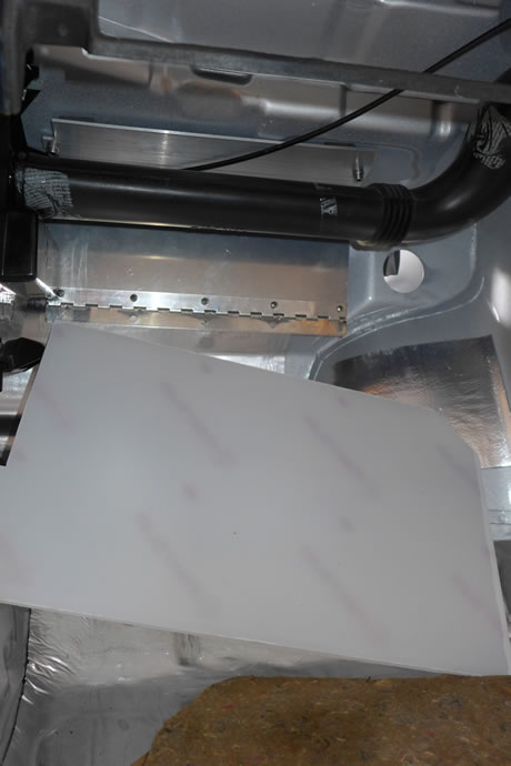
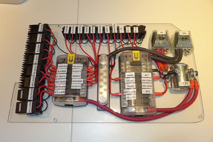
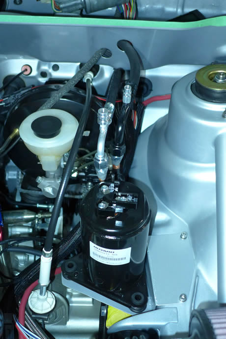
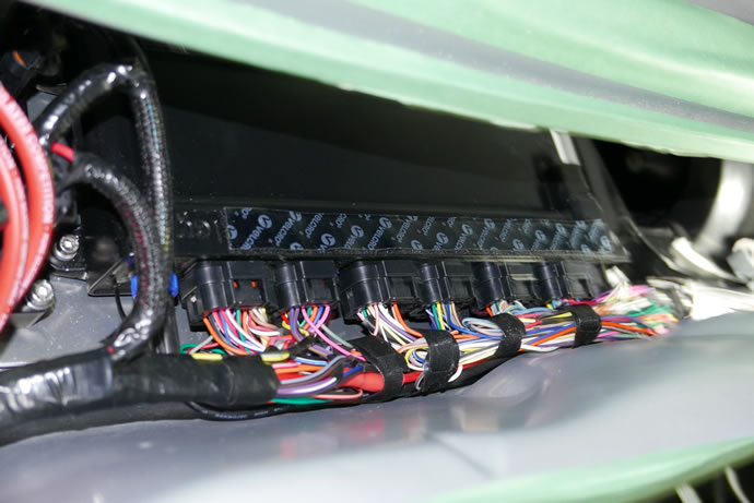
The location chosen for the fuse & relay panel is under the glovebox with a Lexan hinged plate that the fuses and high powered relays are mounted to – remove 2 allen-head bolts and the panel will drop down for servicing needs. Or remove 5 screws and pull out the glove box and service the panel without dropping it down – but you will want to reach in and pull out the passenger side air duct to make it easier to see what you are doing. The original fuse panel location is now occupied by the A/C compressor control module.
Audio System
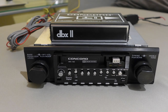
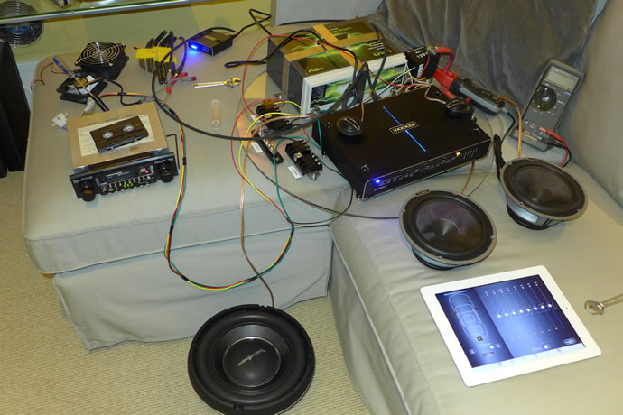
My choice for a head end unit was to re-source my original GTI’s Concord HPL-130 cassette deck which was the top unit back in 1982-1983 and I was lucky enough to locate a NOS unit from the original Los Angeles Concord dealer – it doesn’t do anything other than look pretty mounted in the dash but it does remotely turn on the power amplifier, allowing a smart-phone to connect via Bluetooth for audio streaming purposes – the cassette deck can be played but it simply doesn’t sound a good as a digital streaming source.
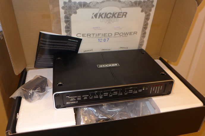
The Kicker IQ1000.5 amplifier is a very sophisticated audiophile grade product with 5 channels, each with their own programmable cross-over frequencies and slopes, 30 band EQ per channel, individual time delays, and more – the TweEQ iphone app and Android app can be used to program the amplifier but I have found that it is much more reliable to plug a USB cable directly into the amplifier and use the Kicker Tweeq app to edit on a larger screen with a mouse or trackpad. The audio system has been professionally calibrated for flat frequency response.
Kicker IQ1000.5 Amplifier related Apple iOS software: https://apps.apple.com/us/app/tweeq/id1001591656 and PC application: https://www.kicker.com/tweeq
My IQ1000.5 Config file: www.derekspratt.com/Misc/GTI_Kicker_TweEQ_Config.CFG
All electrical/electronic lines from the front dashboard to the rear of the car run inside the frame rails on the passenger side of the chassis as follows:
4/0 +V battery cable to the starter and front electrical fuse/relay panels
Remote amplifier ‘power on’ signal from the Concord HPL-130 head unit
+V battery voltage sense line to the ECU
Battery current monitoring circuit signal to the ECU
Concord HPL-130 head unit antenna coax cable
Remote camera video cable
Concord HPL-130 stereo RCA level output cable to the power amplifier
Power amplifier remote control cable to the dash module (sub-woofer parameters and hands-free mic)
Rear lights wiring harness: turn signals, brakes, backup, license plate and side running lights, rear hatch courtesy light
Nitrous fluid line from the bottle to the engine
Nitrous bottle heater line
There are also additional speaker output cables and the cooling fan cable running separately down the centre of the chassis thru to the front console under the carpet.
A/C System
The Mk1 GTI had A/C as a dealer installed option, adding almost 100lbs of weight to the front-end of the car with an awkwardly mounted compressor and lines. Most GTIs were delivered to their owners without A/C, and in those days most people, including myself, didn’t seem to mind leaving the windows rolled down, but today it seems crazy to own a car without A/C, or electric windows for that matter. I had 2 rules to obey: minimal weight and no parasitic power loss from the engine so an electric A/C compressor was the only path forward. Belt driven A/C compressors have >10,000BTU of cooling capacity while a 12V compressor has 3,000BTUs of cooling. The good news is that most of the 10,000BTU capacity of automotive compressors is not used during steady-state operation – only the initial cool-down period, so 3,000BTUs is not that far off the amount needed for continuous use.
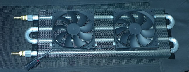
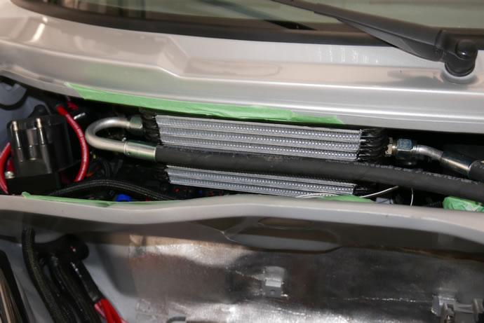
I ended up mounting a small condenser under the car with 6 waterproof fans blowing air across it, and welded up 1/3 of a GM evaporator core to mount next to the blower in the rain tray. The system only weighs 20lbs total and can cool incoming air from >90 degrees F to around 75 degrees F at a medium blower setting and the compressor running at 80% of full speed, pulling around 25amps of current.
Fuel System
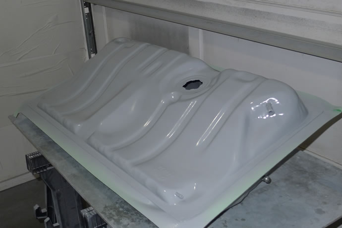
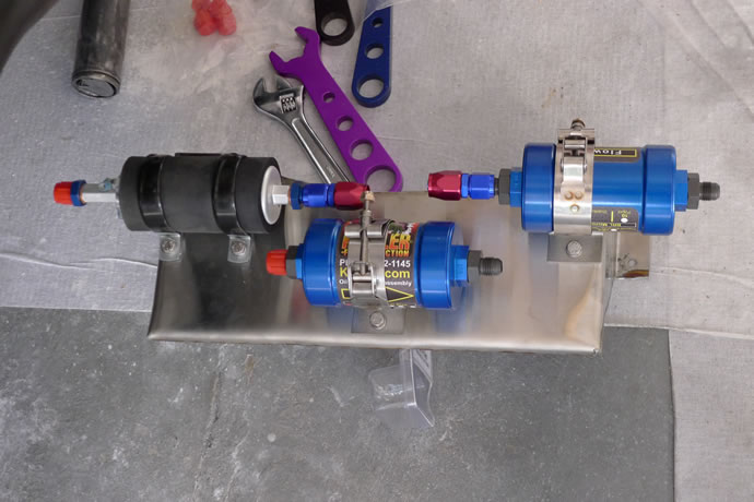
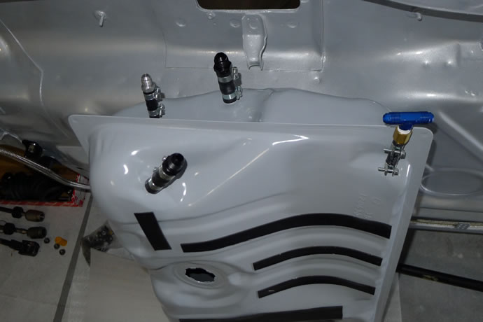
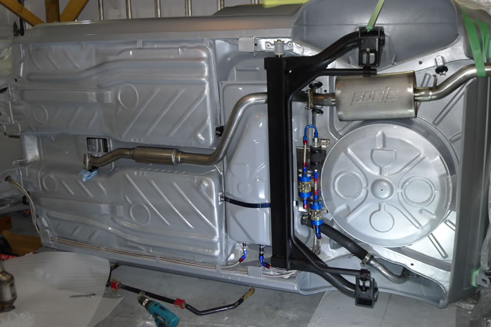
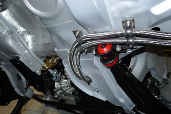
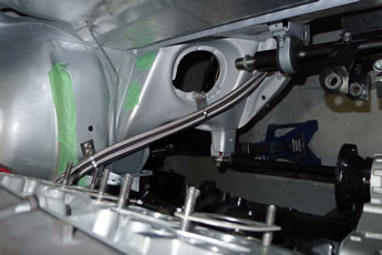
A new epoxy coated fuel tank has been mounted with stainless steel straps and a mounting panel has been placed between it and the wheel well under the back of the car where the fuel pump and filters are mounted for easy servicing as required. Filter housings are CNC aluminum with a 25 micron inlet filter and a 10 micron outlet filter with stainless steel braided fuel supply and return lines with AN fittings run inside the chassis frame rails to the engine. The fuel tank employs a 2 way pressure release valve that keeps fuel vapours contained in the tank unlessdifferential pressures exceed 1psi. Up at the engine the dual fuel injector rails have their pressure controlled by a high volume regulator.
The timeline story of the electrical and fuel system building process
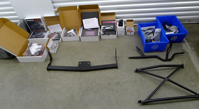
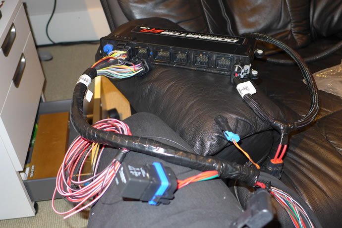
I picked up the complete ECU system (sourced from Kinsler Injection) - boy there are a lot of wires that will need to be connected. I also picked up the remaining engine sensors and plumbing components from Techtonics ... - May 3, 2014
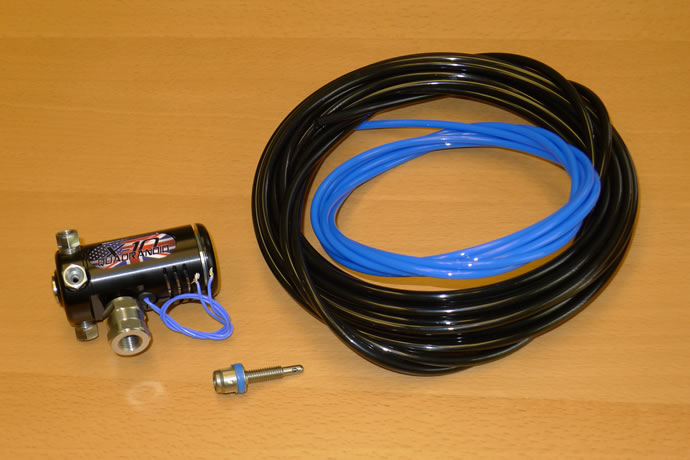
NOS Wizards Quadranoid, a dry flow nozzle, and small ID plastic tubing ...
I am epoxy coating the fuel tank before installation - July 20, 2014
With the final painting complete I can now get on with planning and executing the fuel and brake system installation - August 17, 2014
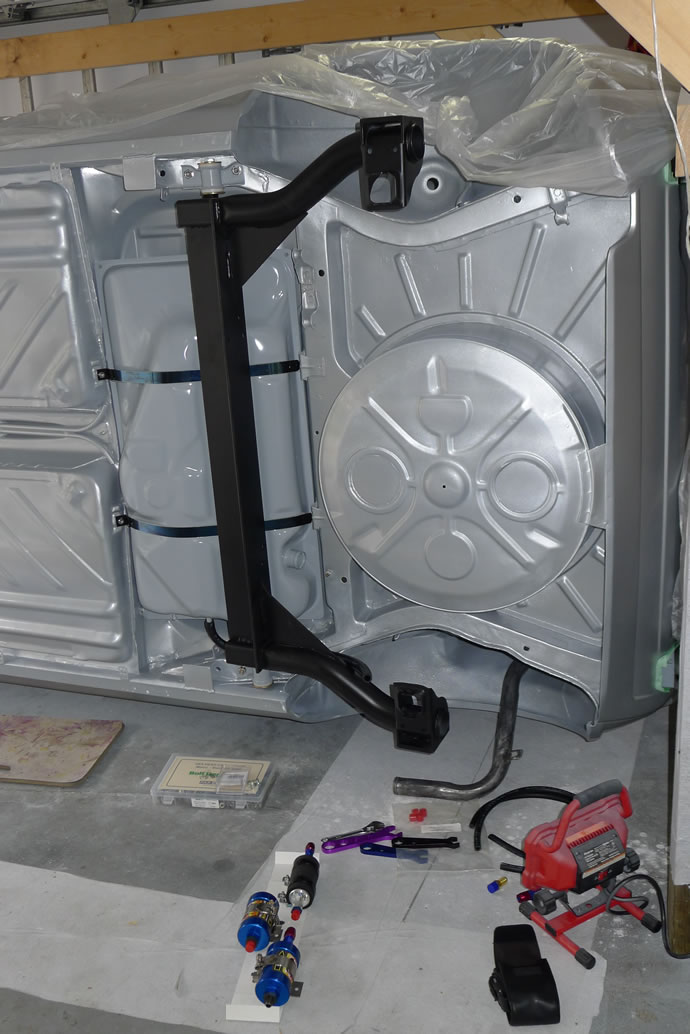
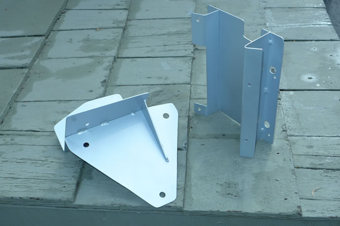
It was a tight sqeeze but I managed to route the fuel tank breathers together such that I can now install a rollover valve in the fuel filler neck area of the wheel well. I got the pump and filters final-mounted and the hoses routed as well. The Techtonics SS 2.25" exhaust system installation has also started but I was very frustrated with a few things that are only partially resolved at this moment: a serious interference fit with the driver side tank strap which required that I fabricate a bracket to allow the removal of the strap, plus I can't get the resonator to sit in the middle of the tunnel without an interference fit with the front hanger on the side of the tunnel (I think I will end up cutting and rewelding some pipe to solve this). The bottom line is that all of the really hard problems with the fuel system are now behind me and the exhaust system issues are on the way to being solved. I will need to mount the engine and exhaust racing header before making any final decisions on the exhaust system though - September 1, 2014
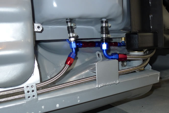
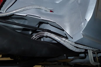
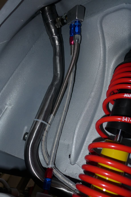
The final fuel system plumbing involved fabricating some stainless brackets to allow for clean and safe mounting of the supply and return lines - November 11, 2014
I bit the bullet and upgraded from the Holley HP EFI system to the full Holley Dominator EFI system with its endless # of inputs and outputs. In the end I needed to control more things like 2 PWM fan outputs, a PWM water pump output, and more sensor monitoring (e.g. a second water temperature sensor in the radiator allows me to monitor the difference between the rad and block temperatures and adjust pump flow rates and/or put a restrictor plate into the system to avoid 'block shock'). I am also going to use the Racepak UDX LCD console which communicates with the Holley EFI ECU via can-bus - January 18, 2015
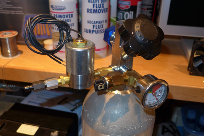
I finally sourced all of the fittings required to create a 'push' compressed air nitrous system (4500psi carbon air bottle with a 2900psi output regulator, a 3000psi solenoid, a 550-1250psi adjustable nitrous pressure switch, and the tricky NTP to BSPP adapter required to connect the air quick-disconnect fitting) - March 8, 2015
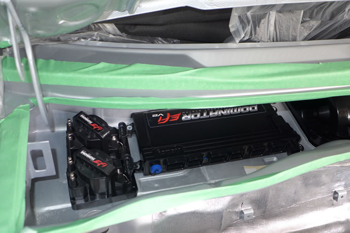
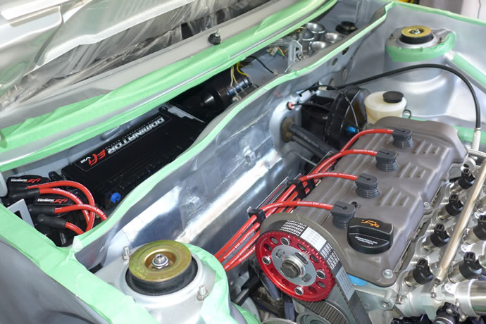
After fighting with the old heater valve cable for about 2 hours (trying to lubricate it so that it would slide smoothly and open/close the heater valve) I gave up and found a replacement Gemo p/n 161819837 on ebay that looks like it will work fine in my mk1 application. I then fitted up the remaining cables that were in perfect working condition and mounted the heater/HVAC box in the chassis with its new gaskets. I was then able to hook up and complete the coolant system lines in the engine bay and pressure test the complete system to 15psi - success! I was also able to install many of the engine sensors and started to design a mounting bracket for the Holley Dominator ECU and ignition coils that will be placed in the rain tray on the passenger side (it is all weather proof but won't really see any water where it will be placed) - April 25, 2015
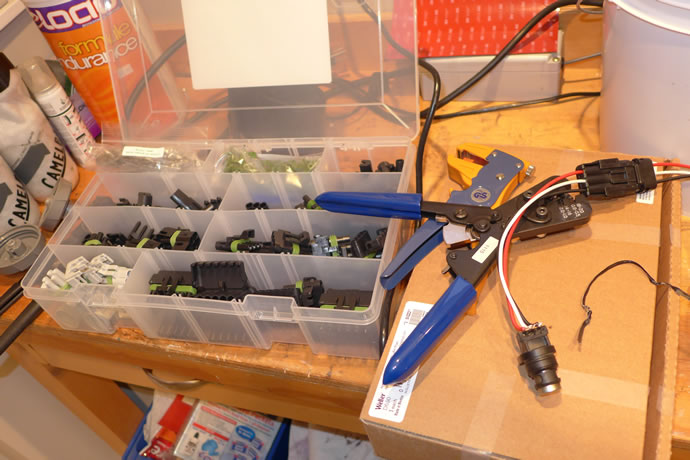
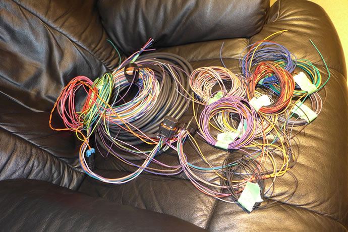
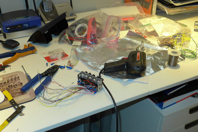
I am starting to lay out the wiring harnesses and plan my connectors (a combination of metripack and weatherpack connectors). I had to cut away all of the electrical tape on the main ECU wiring harness as Holley had placed the fuel pump & injector relay and fuse in a crappy location for my project, same with the main power fuse.
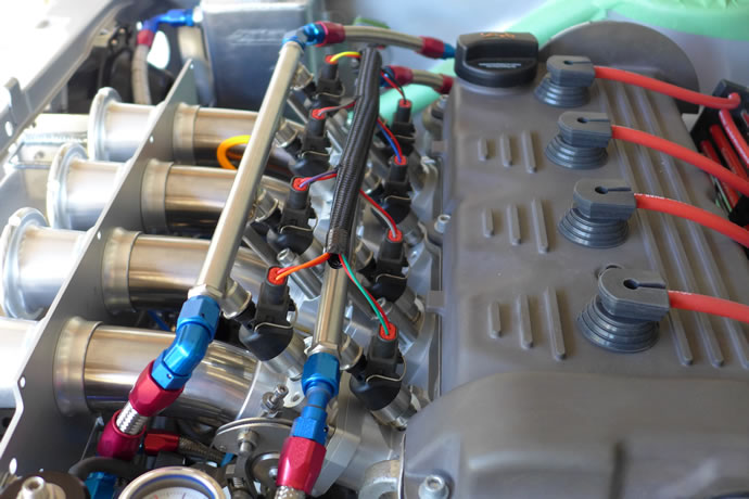
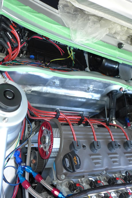
I semi-finished my ECU/ignition system mounting system/plate, ordered and wired up the custom Magnecore KV85 silicon ignition wires and fabricated a wiring loom to hold the wires to the back of the cylinder head. I am pretty happy with how they look.
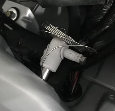
I sorted out the remaining engine sensors and tested/modified them to suit my project. The cam and crank sensors have given me the most challenges. I had to basically build a custom cam sensor earlier on in the project, and for the crank sensor I adapted a late model Bosch hall effect sensor that didn't quite fit the VW ABA block so I had to grind away at it a lot and also solder up a custom connector that would not hit the block but in the end I was rewarded with a high quality digital output to the ECU. For the cam sensor I got it setup properly to trigger at 180 degrees before Cyl #1 TDC which is what the ECU wants to see. Just prior to firing up the engine for the 1st time I will test all of the ignition timing with the injector harness disconnected.
Here is a list of the main engine sensors (email me if you need the p/ns for the mating connectors):
Bosch KS-R knock sensor, p/n 0 261 231 047 (analog peizo output, ECU set to monitor at 7.2kHz)
Bosch Hall-Effect Speed Sensor HA-P, p/n 0 232 103 037 (requires 1k pullup output resistor)
BBHME2000 Hall- Effect Cam Sensor (requires 1k pullup output resistor)
- May 12, 2015
My new Magnecore ignition wire set and loom ...
Comparing the stock ABA inductive crank position sensor IA-C (p/n 0 261 210 136) to the later hall-effect sensor I used ....
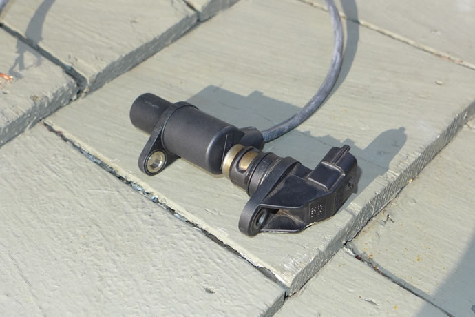
Modifying the later model hall-effect sensor ...
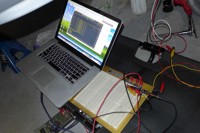
Testing the crank position sensor ...
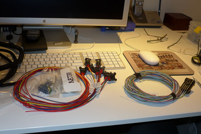
The past 10 days have involved a lot of electrical parts sourcing and planning as I have come to the realization that it is simply not practical to just wire up the engine ECU and fire up the engine without planning and executing the foundational electrical system before hand. Something as simple as routing a wire thru the firewall requires that the location of the wiring harness be pre-determined and also that any gaskets already be in place (and the gaskets are sometimes hard to source). I also made the tough call to bail on using part of the stock wiring harness and instead will completely rewire the GTI end to end so I have made up a nice flip-down wiring panel under the glove compartment that will hold all of the distribution panels/fuses, and relays. I also determined that a 20AH Lithium Pros Battery would be my power source (Lithium batteries have a very flat discharge curve and can be deep discharged making a 20AH capacity battery equal to a 30AH lead-acid battery and it weighs 7.5lbs vs 30lbs) so I ordered one. I plan on running 1/0 flexible welding wire from the trunk to the wiring panel, passing thru a remote/wireless controlled 150amp disconnect switch and a 200amp current shunt (to allow the ECU to monitor the charge/discharge rate of the battery), then controlling the switched +12V via a traditional 150amp continous duty solenoid which will then feed all of the fuse panels and relays. All mechanical switches will be replaced by ECU/Digital display touch panel controlled virtual switches, including things like the emergency flashers, various lights, seat heats (continously variable heat control by computer) etc. Even the old turn signals and driving lights will be controlled via the virtual switches by feeding the dash/stalk switch outputs to the ECU inputs and then the ECU outputs will drive the 50% duty cycle relay controlled turn signal outputs, etc. - all using the Holley Digital Dash unit (by using the Dominator ECU I have tons of assignable I/O pins so I might as well take advantage of the same technologies used in software controlled cars like the Tesla). I also sourced a Kicker IQ1000.5 1200W RMS amp for the audio system which is all software programmable and streamed to by bluetooth - May 28, 2015
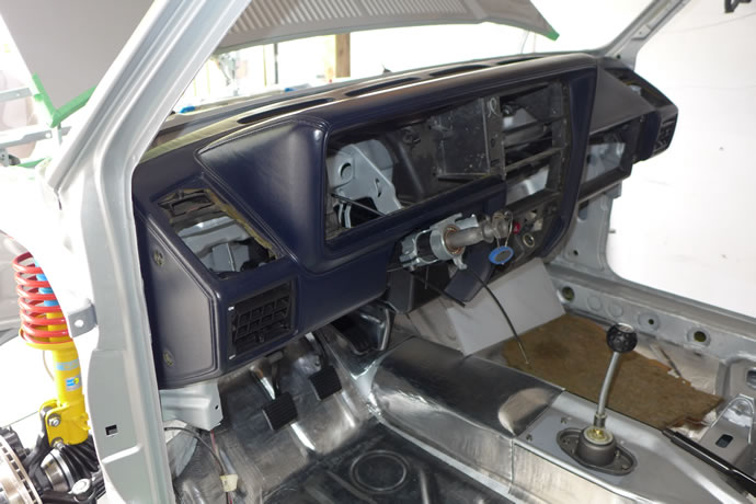
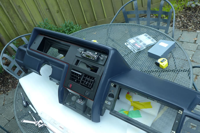
Test fitting in the stock dash to determine wiring panel installation parameters ...
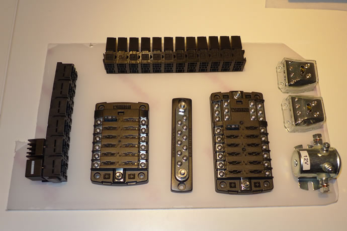
Fabricating a flip down 1/4" Lexan mounting plate for the relay and fuse panels under the glove compartment ...
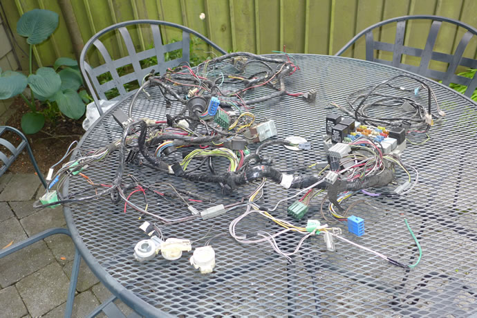
Death to the old stock wiring harness (rats nest) ...
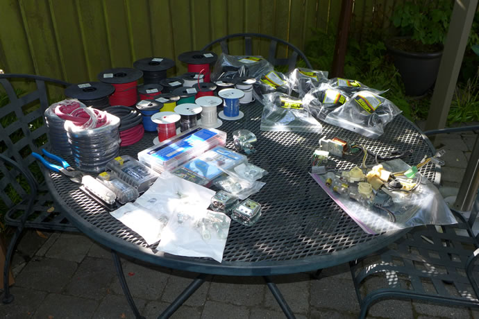
A portion of the wiring materials I will be using to completely rewired the GTI ...
1200 watts RMS with full digital EQ and Bluetooth control/streaming ...
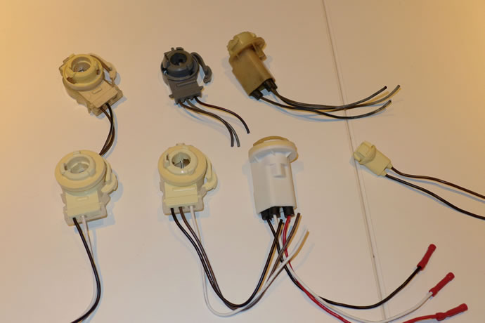
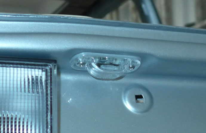
Major score today! I was wandering around the local automotive parts store looking for some electrical supplies and out of the corner of my eye I spotted what looked like a VW mk1 US spec light bulb holder on the rack of GM connectors. On closer examination I located what looked like all of the major bulb holders for my Rabbit GTI and took them home to verify that indeed these were the correct replacement parts. This makes total sense as the US VW engineers would have had to meet US DOT lighting requirements so why not dive into the local Detroit parts bins and borrow a few things? Here are the part #s:
Front turn signal bulb holders: GM 88860442
Rear side turn signal bulb holders: GM6298892
Rear 2 circuit bulb holders (4 required): GM 12003758
Rear 3 circuit bulb holders (4 required): GM 12003759
All of the bulbs for these holders can be sourced in LED format which is what I have done, with an eye on keeping the same level of brightness as the original bulbs (you have to be careful as most LED replacement bulbs are lower brightness) - June 2, 2015
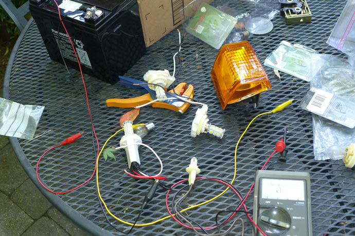
I got all of the fuse blocks, regular and micro relay blocks arranged on the panel that will mount under the glove box and will drill holes and start to mount everything this weekend. I also got the LED lights mounted in the housings with the new GM bulb holders and tested out their brightness (they modestly exceed the brightness of the OEM bulbs but require a dimmer 47 ohm resistor for the dual brightness settings to match the stock look). There are also a few minor clearancing issues with the LED bulbs that require a bit of work with a dremel to allow them to fit in a few of the holders. Here's the info on the bulbs I used which were ordered from LEDlight.com:
Product ID: 25454
Product Name: S25 27 SMD 5730 10-30V AC-DC
Attributes: Color - Warm White 3000K Base Type - 1156 Single Circuit
Price: $8.61
Product ID: 25454
Product Name: S25 27 SMD 5730 10-30V AC-DC
Attributes: Color - Warm White 3000K Base Type - 1157 Dual Circuit
Price: $8.17
Product ID: 45689
Product Name: T10 Wedge 5 Ultra Bright SMD LED Bulb 1.5W W5W 12 VDC T3 1/4
Attributes: T10 Color - Super White
Price: $3.58
- June 5, 2015
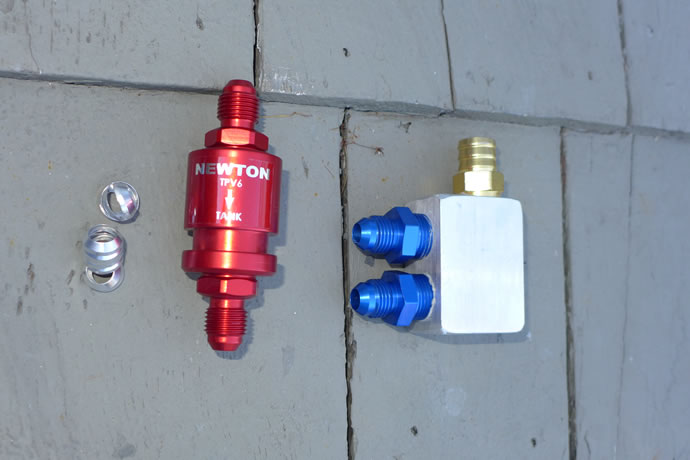
I was tired of smelling raw gas in the garage and did some research on what racers do to safely and properly vent their gas tanks without the loss of fuel vapour and the answer turned out to be a trick invention from a UK company that makes a bi-directional fuel tank vent valve that releases pressure inwardly at 0.05psi (for when the fuel pump is sucking and needs air intake) and outwardly at 0.7psi for when the temperature of the fuel tank as warmed up substantially and excess pressure needs to be released. This keeps the tank vent closed in normal use and nicely eliminates the smell of fuel vapour in the garage. I did also find that the fuel level sender gasket wasn't sealing perfectly so I added some silicon sealant to it and that solved that problem. Finally, I added thin -6AN aircraft crush washers to all of the engine compartment -6AN fuel fittings to ensure that they were absolutely sealed - the problem of sealing AN fuel fittings seems to come from combining fittings from different manufacturers - just a precautionary measure.
I put a ton of time into wiring the ECU harness and installing it into the chassis. I think it will take another 2 weeks to complete all of the chassis/engine/ECU wiring and then it will be time to finally fire up the engine - June 15, 2015
The TPV6 fuel tank vent value assembly ...
ECU wiring madness ...
 '
'
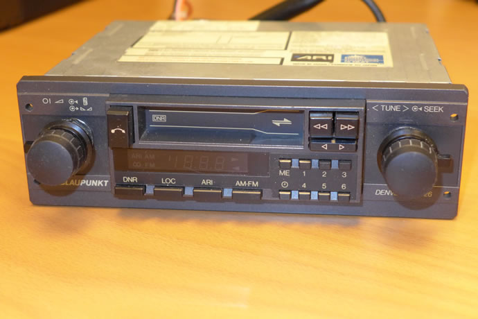
The fuse/relay panel was finished and installed in the car - now the wiring looms need to be terminated and attached to the relays and fuse blocks. I sourced original AM/FM cassette decks for the car as well: A Blaupunkt Denver SQL26 which looks very close to the OEM cassette deck (does anyone have a hi res photo of the original one?), and a mint condition Concord HPL-130/dBx AM/FM cassette deck (this is the model I installed in my GTI in 1983). I also got more wiring done in the chassis - June 29, 2015
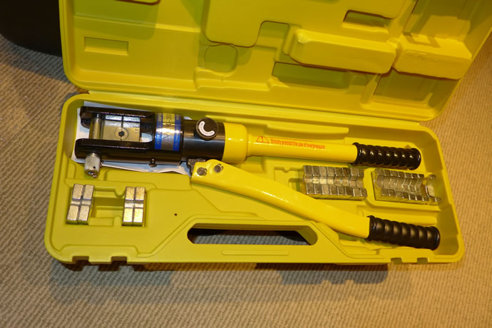
My hydraulic battery lug crimper (12 tons of force) - a worthwhile $75 Amazon purchase ...
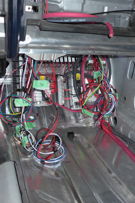
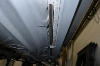
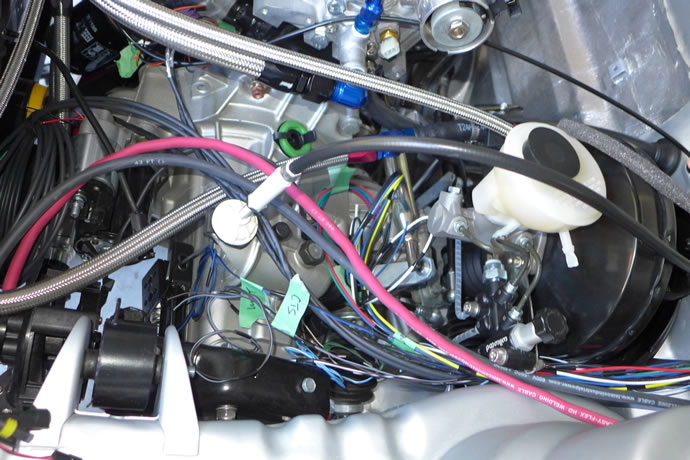
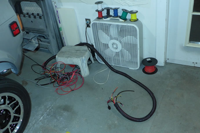
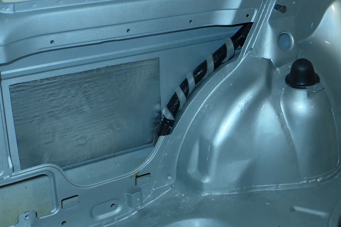
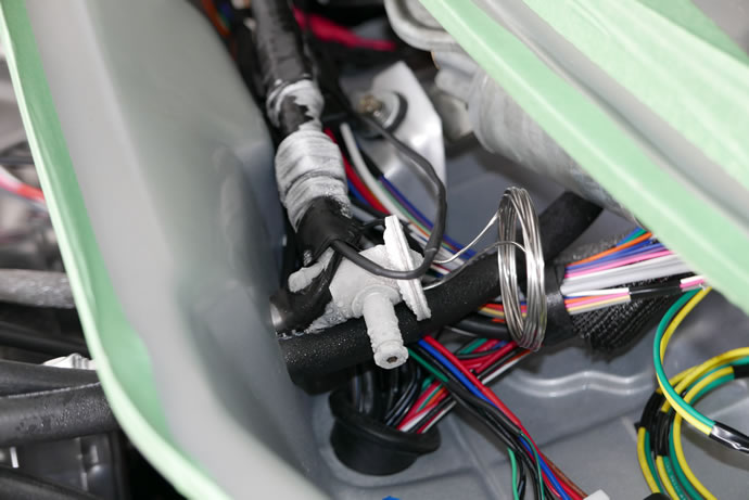
As part of my engine ECU wiring I had to run the low voltage and high voltage wires next to each other for a short distance so I did a careful job of shielding them fully. These photos were taken before wrapping all of the shielding in protective tape and then applying the final plastic conduit to them - July 22, 2015
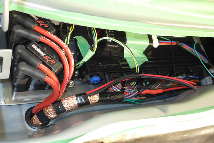
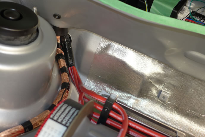
[Background: as a young electrical engineer 30 years ago I designed power supplies and battery charging systems for mobile devices]
I was very excited to be able to use the latest greatest automotive grade Lithium ion ferrous phosphate battery technology from Lithium Pros as they are vasty superior to lead acid batteries in several ways: very flat discharge curve (the battery voltage stays high); high high cranking amps without voltage drop (cranking at 12.8V, not 10-11v); very fast charging (all of the available energy from the alternator is immediately stored); many times greater cycle life; deep discharge capability (you can use all of the capacity without damage); and light weight.
But the negatives are: poor performance in sub-zero temperatures; and a less than ideal match to standard automotive alternators that put out 14.4V when Lithium batteries don't want to be charged at more than 3.4V/cell = 13.6V. On-board battery management systems try to shunt the additional voltage and excess current thru internal discharge resistors and it sort-of works but the ideal situation would be an intelligent computer controlled alternator regulator that can rapidly charge the Lithium battery and then back off ... enter my latest project idea ...
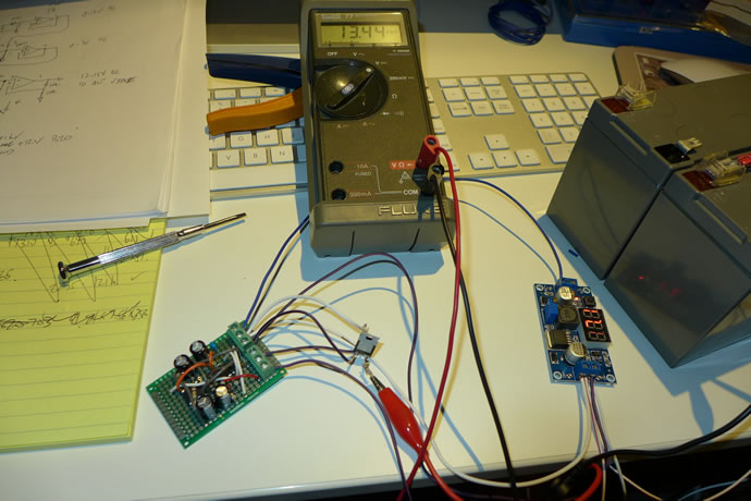
I built a circuit that allows full alternator voltage up to 13.6V and then limits it to 13.8V - it does this under ECU control by monitoring the battery voltage and then spoofing the alternator into thinking that it has reached 14.5V by outputting higher than actual voltage back to the alternator 'sense' wire. It uses a charge pump circuit to get 16v to the op amps, and the PWM output of the ECU to send signals to the circuit to increase or decrease the Vsense line. It works perfectly and now I have a charging system that won't limit the life expectancy of the $1200 battery I have.
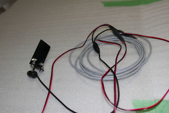
And I completed the associated battery charge/discharge ECU monitoring circuit which consists of a 75mV/200A shunt in series with the battery and a bi-directional differential voltage amplifier/monitor that puts out a 0-5V signal to the ECU (2.5V = 0 amps, 0V = 66 amps charging, 5V = 66 amps load) ...
I also received my midnight blue headliner material from SMS - it is a perfect match to the VW OEM fabric and is nicely foam backed ... - November 17, 2015
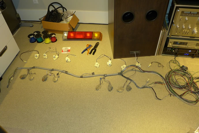
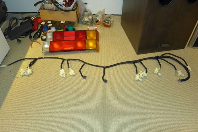
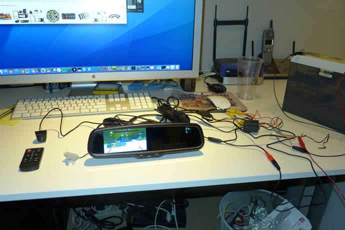
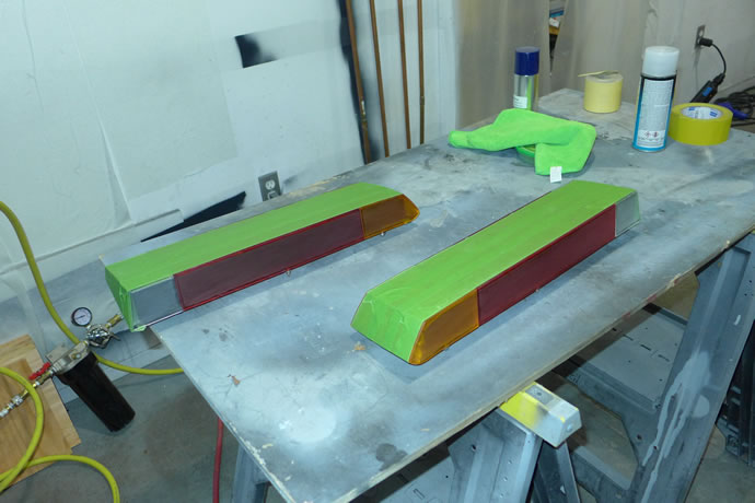
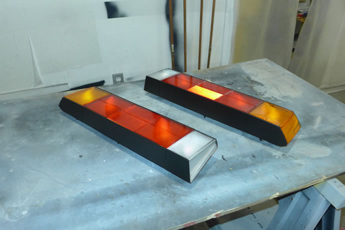
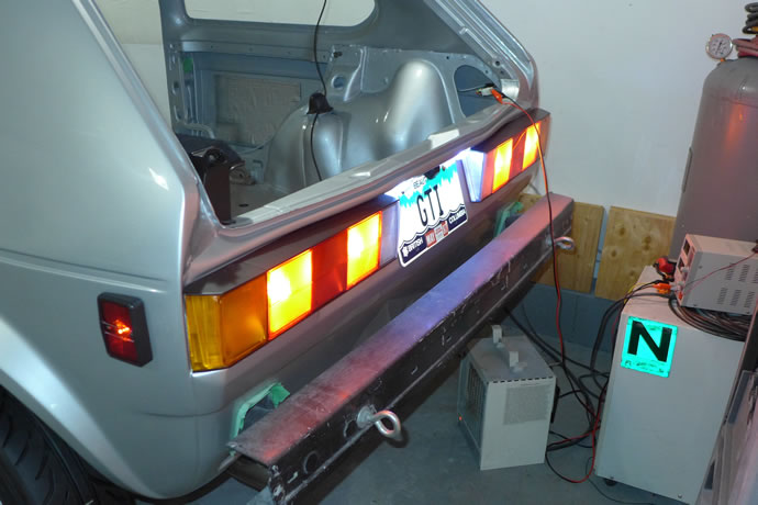
For the last few weeks I have been working on the rear wiring and lights, starting by building a new rear wiring harness with all new connectors and LED lights (see prior posts for p/ns), plus I worked on coloring the Hella replacement tail light assemblies to be a hybrid of a US and Euro Spec look to them (I am also building aluminum/carbon fiber bumpers that will be a hybrid of US and Euro Spec look to them - shaped like the US bumpers but scaled a bit smaller and closer to the body). I got the powered radio antenna installed in the back, plus sorted out the backup camera mounting and wiring, although I blew up the camera by connecting it to 12V when it needed 3.3V. I also got the 12.9 grade rear axle mounting bolts installed with the Lella AutoSport 15mm spacers - January 17, 2016
The old wiring harness ...
The new wiring harness ...
The Boyo rear view mirror and backup camera ...
Painting the Hella US Spec tail-light assemblies to look 1/2 like the original US Rabbit GTI units and 1/2 like the Euro spec units (black top and bottoms but no black lines in-between the lens) ...
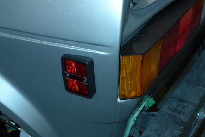
Drilling out the sheet metal screw holes for the side markers and license plate lamps to accept M4 slainless nuts and bolts (I will use black oxide button head screws for the side markers when they arrive) ...
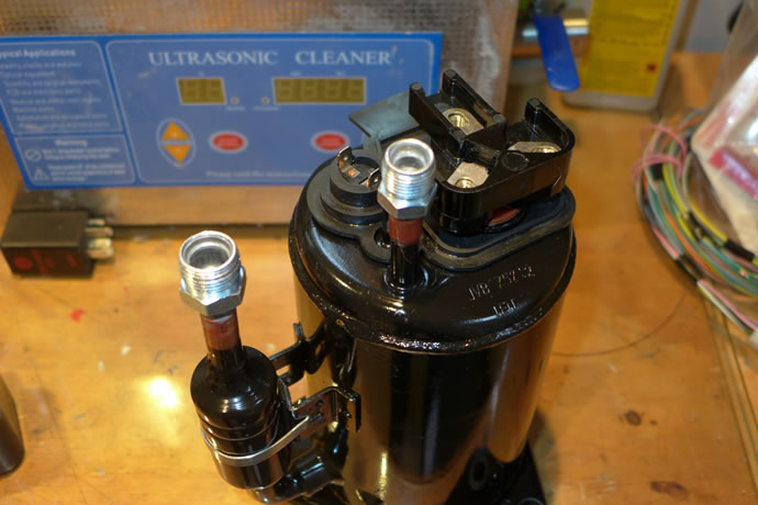
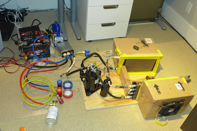
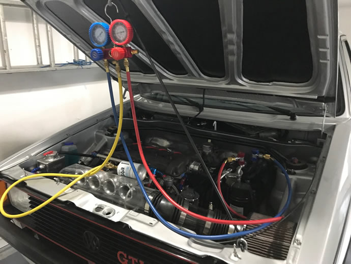
I finally got to the point where I had all of the parts necessary to assemble and bench test the electrical A/C system. I used low temperature aluminum/copper solder (500 degree F) and I didn't really do a very good job on the receiver/drier connectors as I didn't apply the massive amounts of flux that that particular solder requires - so I had to re-solder a few places and still need to chase down a few remaining leaks (I have ordered Harris Al-Cor brazing wire and will re-do all of the connectors and I may also switch over to flex lines ...). All of the copper compression fittings are leak-free but another set of leaks occurred after 24 hours at the NPT teflon tape fittings as the POE oil in the system actually dissolves teflon tape - so I replaced the white tape with yellow gas spec tape and it seems to hold better (we'll see ...). The system was charged up with R134a refrigerant and it came to life. It will need tuning to bring out its maximum potential: the oil coolers I am currently using as the evaporator and condenser cores aren't very thermally efficient when used in an A/C system and so I will look more into finding small A/C cores that will fit my application, plus I need to determine the ideal R134a charge load - I added too much at one point in my testing and the performance dropped almost to zero (I think the low side pressure should be around 25psi and it was up to 40psi). With a medium-high fan setting I saw about an 8 degree F drop in air temperature coming thru the evaporator and I'd like to see more like 10-15 degrees drop (this compares to commercial systems that are >4x more powerful and can drop the air temperatures from 80+ degrees F to below 50 degrees F).
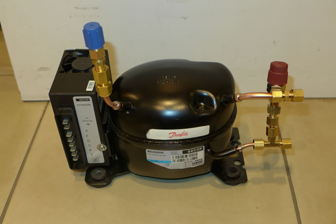
I thought I should provide some basic automotive A/C background info and relate that to this project: A typical crank/belt driven automotive A/C compressor is capable of 10-20000 BTU/hr output capability. Due to the law of thermodynamics heat/energy removal (a thermal transfer process) isn't a watt for watt 1:1 relationship. e.g 1 watt of energy input into the compressor translates into approx 2 watts of energy removal from the air. For my tiny little Danfoss BD250GH compressor, which draws around 10-15 amps at 12.5V, or up to 200W, it provides up to 400W of energy removal, or around 1300 BTU/hr. I could upgrade my compressor to 2 other available units (http://www.seanhylandmotorsport.com/blog/12-v-air-conditioning-compressor-how-can-you-decide-if-one-is-right-for-you/) that consume 20-31+ amps of power for between 3000-6000 BTU/hr of cooling capacity in a package that is roughly the same weight and size (7-10lbs) as my Danfoss compressor (with easier to manage automotive A/C fittings pre-installed - but the compressors have less complex electronics that can't speed up and down the compressor as energy demands change - you are limited to turning them on/off). Air weighs 0.04Kg/cu-ft and the fan I am testing with is around 150cfm, which means that the mk1 golf with its approx 80cu-ft of interior volume would have its air exchanged every 30 seconds and in that case my little compressor is removing around 3-4 degrees C of temperature from that volume of air. Dry air has a specific heat factor of 1000J/kg-C (in other words, it takes 1000J to raise the temperature of 1 Kg of air 1 degree C and 1W = 1J/s). My fan is moving 150cfm or 2.5cf/s, or .1Kg/s or 100W per 1 degree C of cooling = 300-400W of cooling, so my system is pretty much running as expected. If I slow the fan speed down 70% to an equivalent to a 'low' blower setting I can then expect the air temperature drop to be around 10 degrees C. And that is with a small Danfoss compressor. You have to remember that the sun radiates a huge amount of energy into the car interior while driving and when a car's interior is hot it requires a huge input of cooling to bring the temperature back down, and that is why 3000+ BTU/hr is a better starting point for a 12V electrically powered A/C system. I think I can make my little 1300 BTU/hr system work effectively but I might end up changing to the larger compressor in the end. This is a big science fair project and so I am learning and experimenting along the way. Fun stuff! - January 24, 2016
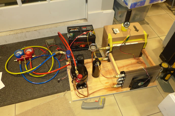
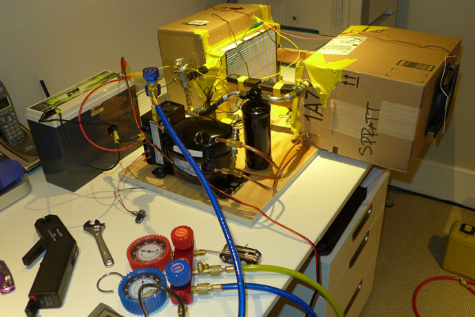
I took all of my new parts for the electrical A/C system and put them on the prototype system: new #6 A/C barrier hose and fittings for the drier/filter unit, lots of temperature sensors to bench test the system, and more air boxes to fine tune the performance and help squeeze every last drop of performance and efficiency from this system (given that it is a bit marginal re. cooling capacity). In the end the amount of R134a refrigerant charge that provided the best performance was 35psi on the low side with the compressor running at max speed (4,400rpm at 13.5amps/13.3V). This provided close to 7 degrees C of air cooling across the evaporator at an equivalent to a 'low' blower setting in the car and a little over 4 degrees C of air cooling at an equivalent of a 'medium/high' blower setting (150cfm - enough to change the air in the cabin every 30 seconds). The performance #s are solid: 160W of electrical energy providing approx 400W of cooling (1,400BTU/hr). Since I have a small racing alternator I cannot afford more than about 15amps of continuous current draw at idle, so if this proves to be too little cooling the next step up in compressors is closer to 2x in both current draw and cooling, and is also 2x more expensive ($1,200 vs $600). I'll install this system and if it is not sufficient for my summer needs and I am not at the edge of my alternator capacity I might upgrade to a larger compressor .... we'll see - February 8, 2016
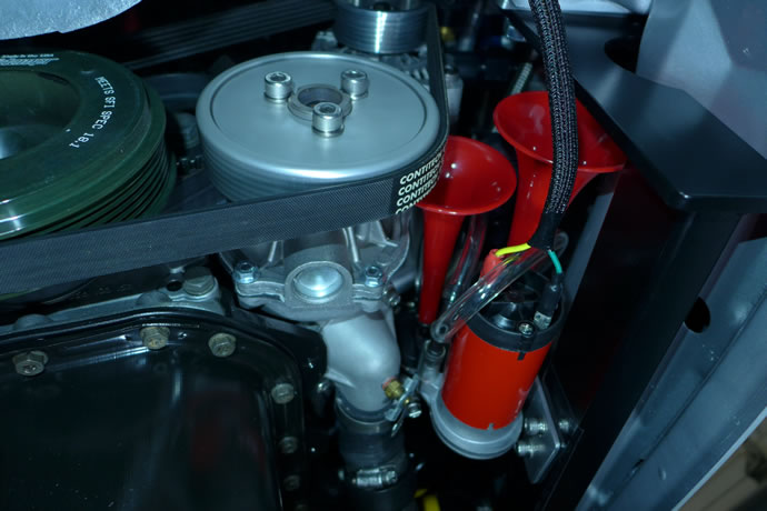
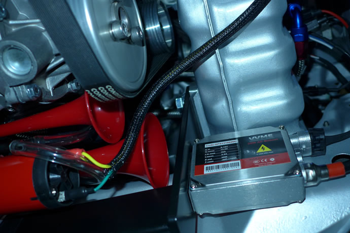
I fabricated an aluminum bracket out of 1/8" material using my new sheet metal brake to mount my Hella air horns (the same ones I had on my old GTI back in the day) - they fit perfectly beside the water pump housing. I then mounted the HID high voltage transformers under the radiator area - February 17, 2016
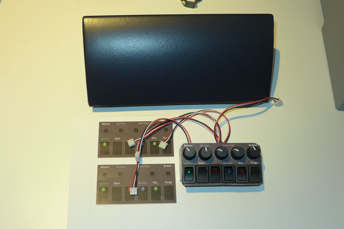
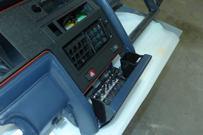
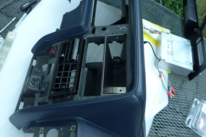
I managed to cut/punch/nibble/bend an aluminum bracket to mount the 6 switches and 5 pots in the ash tray, plus design and print to a durable label with all of the panel info. It barely fits but it does fit and looks the part (I am happy about how it turned out). I'll have to wire up a 15 circuit Molex connector to it and then from there to the ECU next ...
I found an excellent electric A/C compressor from Boyard in China that is a 2.5x capacity step-up from my Danfoss compressor that I had bench tested. Here are the differences:
Danfoss BD250GH: 2.5cc cylinder volume, 2500-4400rpm, max 12amps@13.5V (162W) to produce approx 350W of cooling (1200BTU/hr - a COP efficiency of 2.1), 11.6lbs with controller, results in a drop in air temperature of around 5 degrees C at mid-range blower fan settings. Variable speed so current consumption can be reduced.
Boyard JVB075Z12 : 7.5cc cylinder volume, 2500-3700rpm, 25amps@13.5V (340W) to produce approx 850W watts of cooling (2900BTU/hr [higher COP efficiency of 2.5] of cooling at 3300rpm (so at 3700rpm it will produce closer to 3250BTU/hr at 30amps), 16lbs with controller, should result in a temperature drop of closer to 15 degrees C in comparison to the Danfoss unit at 3700rpm.
I am waiting for new A/C connectors as I will switch completely over to #6 and #8 reduced barrier A/C hose and fittings given the larger capacity of this unit. As a variable speed compressor the current draw can also be substantially reduced as required - my ECU will control the compressor speed based on cooling system demands - March 2, 2016
The new ash tray control panel coming together ...
My 3000BTU/hr Boyard A/C 12V compressor and controller arrived ...
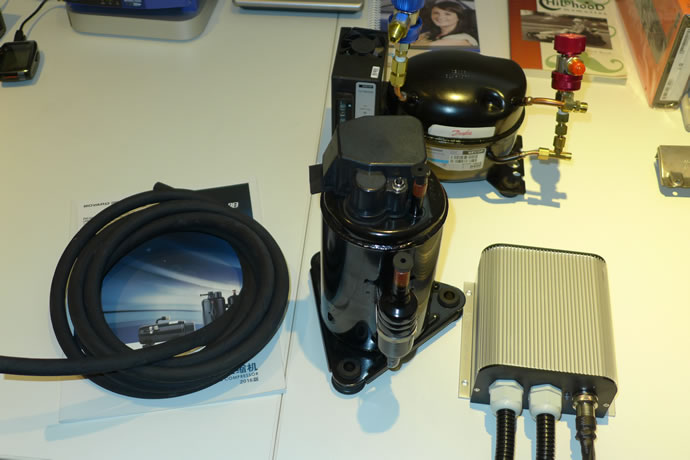
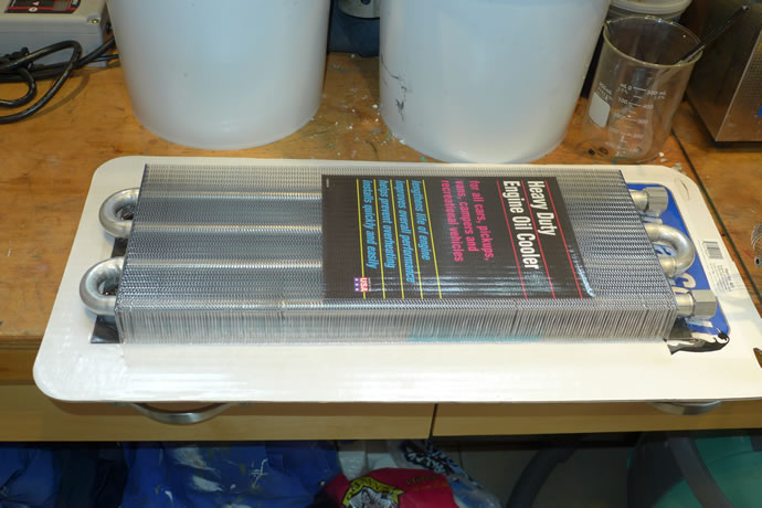
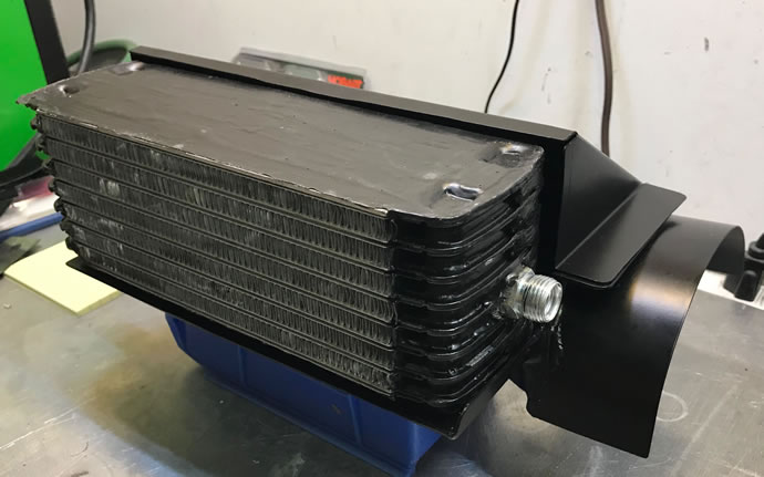
And the larger oil cooler which I will mount under the car and use for my condenser ...
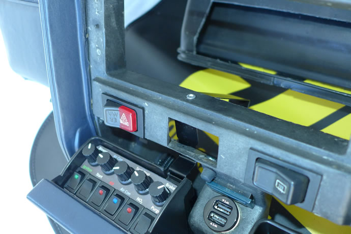
I got the ash tray control panel wired up, test mounted, and built a wiring harness to connect it to the ECU, then I completed the wiring and installation of all lights in the rear of the car, and then built and installed a front-to-rear wiring harness that runs inside the frame of the car, then I connected the wiring harness into the electrical panel and ECU at the front of the car, and also sorted out all of the dash and stalk wiring components that I will use (a mix of old and new), plus I got fairly far into building the wheel well audio and battery system Lexan mounting solution. Finally, I machined and installed the #6 and #8 A/C fittings onto the new Boyard A/C compressor and then assembled and bench tested the system: was a big improvement over the prior Danfoss compressor, putting out >800W of cooling power (almost 3000BTU/hr), vs. 350W for the Danfoss unit. This translates into an 8-10 degree C temperature drop across the evaporator at a medium to high blower speed setting which will make it an effective A/C solution for outside temperatures of up to 30 degrees C or more, at a typical 15-25amp current draw - March 27, 2016
Wiring up the ashtray controller ...
Test fitting the controller ...
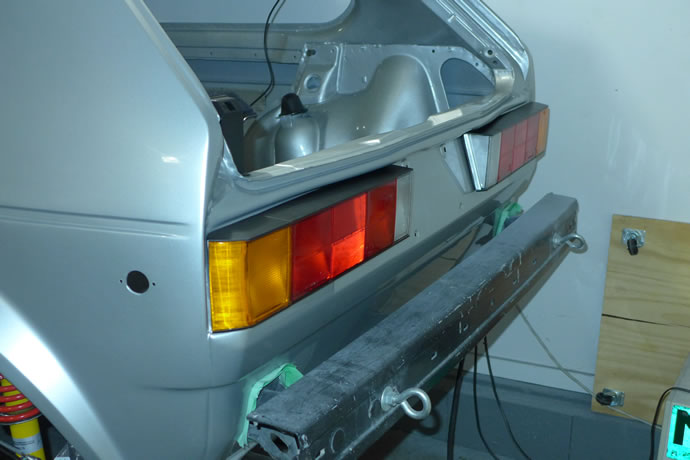
Finishing the wiring and mounting of the rear lights ...
The partially completed wiring assembly used to connect the front and rear of the car together ...
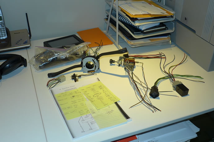
The new dash stalk assemblies and original light switch and wiper electrical components that I am wiring into the computer and the rest of the electrical circuits ...
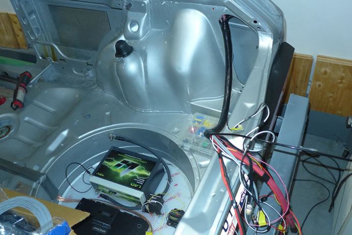
The partial installation of the front to rear wiring assembly ...
Mounting the #6 and #8 'male insert o-ring' fittings to the A/C compressor ...
Bench testing the new A/C system ...
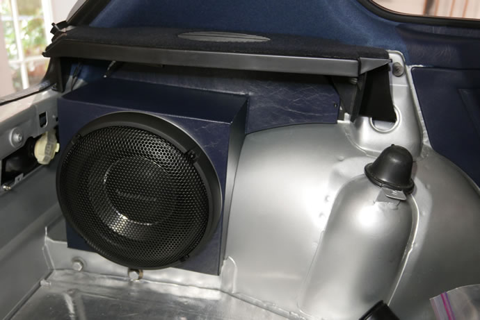
The partially assembled wheel well audio electronics and battery system ...
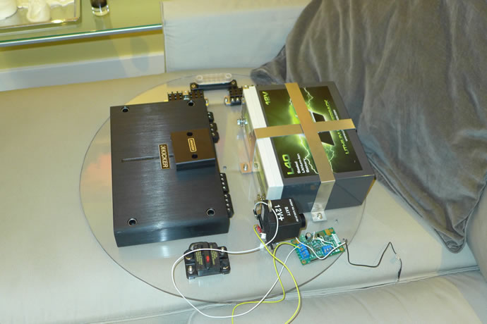
The complete audio system was setup and tested (a combination of vintage and state of the art components) - it was a success. The Lithium battery and audio system was then installed in the car while the dash was prepared by fabricating a mounting bracket for the Concord tape deck, plus the ash tray control console stops were fabricated and installed. The A/C system was bench tested for current consumption at different compressor speeds, and another A/C compressor controller was ordered that has a shorter 5s startup delay so I can duty cycle the compressor to achieve even lower cooling capacity. Mounting brackets were fabricated/welded up/painted for the A/C compressor and controller unit and everything was test mounted - again, a success. Finally, the A/C condenser was assembled with water proof fans and was mounted under the car - April 14, 2016
Testing out the complete audio system ...
Fabricating and installing the tape deck mounting bracket ...
Fabricating and installing the ash tray console 'stops' ...
Fabricating and installing the A/C compressor and controller mounting brackets ...
Mounting the waterproof fans to the A/C condensor and installing it under the car ...
Over the past 2 weeks I machined up a smaller steering column collar, and installed it along with a new top column bearing assembly and ignition switch, put weatherpack connectors on the seat heaters, sorted out all of the h/w and plastic bits needed t put the seats together (and ordered a few missing parts), got the sunroof sorted out as well by refinishing the parts and ordering several new items (the wind deflector and levers, new cable assemblies), epoxied on quick connect o-ring fittings to all of the A/C components, got the front and rear cameras installed and connected to the rear view mirror, and fabricated a transition air box for the evaporator to blower motor ...- May 20, 2016
The front facing camera assembly ...
The epoxied quick-connect A/C o-ring fittings ...
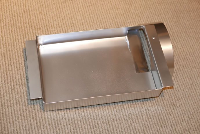
The Evap to blower sheet metal manifold ...
The A/C system has now been installed and tested in the GTI - yes, it is true, I now have a 'cool ride'. Preliminary testing shows around 8 degrees C of cooling but ultimately it will likely end up >10 degrees C as the surrrounding air in the rain tray will be pre-cooled by all of the A/C plumbing - May 25, 2016
The completed ECU wiring bundles prior to the installation of the A/C intake manifold on top of it ...
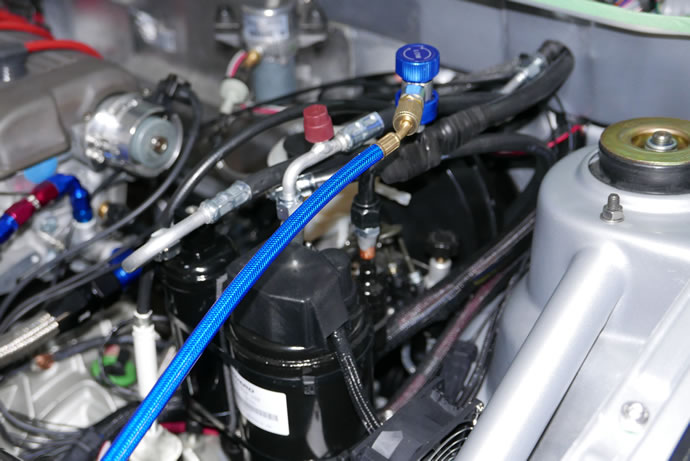
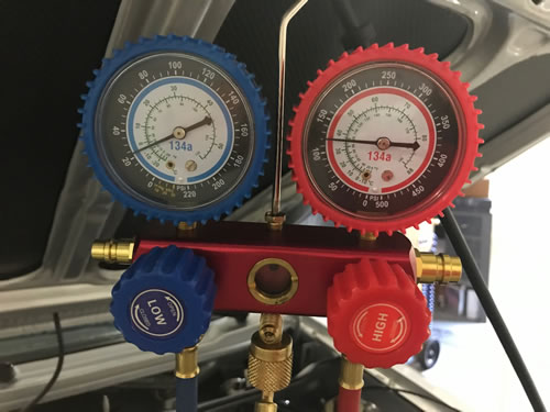
All of the o-ring quick connect A/C hoses were fabricated and installed and then the system was vacuum tested and charged with R134a refrigerant ...
The completed A/C Evaporator system sitting on top of the metal manifold ...
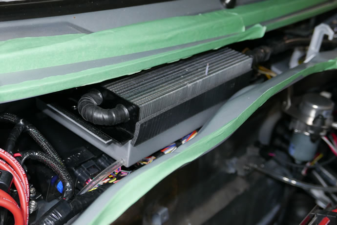
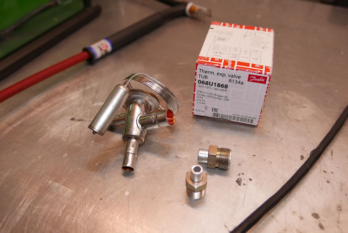
A very frosty A/C TXV thermal expansion valve during initial system testing ...
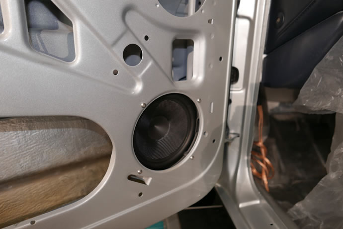
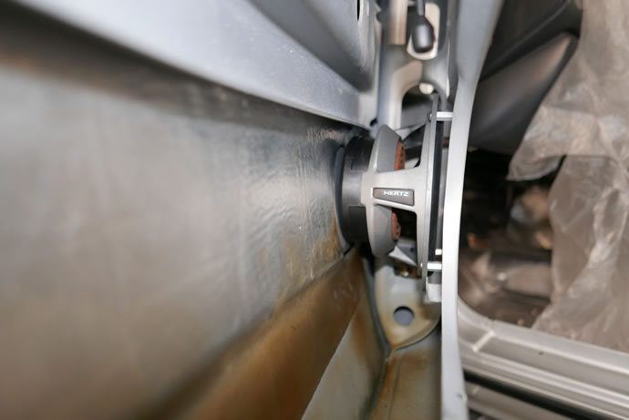
The last 2 weeks were an intense period of battling to put the doors together with the lexan windows and non-OEM windows lifter mechanism, seals, locks, speakers, etc. In the end there was a conflict between the speakers and the lifter mechanism that has caused me to reconsider the design and move towards a mk2 electric lifter mechanism using the hand crank arm as a momentary up/down switch - the video explains why. I am also going to get a local plastics firm to heat bend some Margard lexan to the correct curved shape as the flat lexan sheets don't take the proper shape and are hard to move in the channels. For now the driver window works but the passenger window is fixed - I have the option of simply putting in the OEM glass and the OEM lifter mechanism but I'll try the above approach. The doors look great overall and the sub-woofer ended up working out really well. The latch for the carbon fiber hood had to be re-worked a bit and is now functioning properly. I am T minus 1 week to project completion now ... - August 22, 2016
I swapped out the 1kW A/C TXV for a 2kW unit and the system now pumps more R134a thru the Evaporator at peak compressor speeds, achieving higher cooling efficiency/performance ... - October 30, 2016
The new 8168 Powermaster XsVolt alternator is working perfectly - my LiFePO4 battery appreciates it.
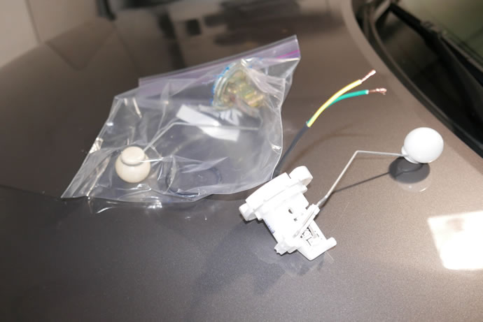
My old fuel tank level sender unit was crapping out so I ordered a new VDO plastic replacement unit which worked out well but I had to modify the connector to create a right-angle version and now all is well.
It is full-on winter here now with snow and ice on the roads (and salt!) but I managed to get a full sunny dry afternoon this last weekend to do some performance testing. I had acquired a Gtech RR performance analyzer to measure 0-60, 60-0, power, cornering, etc. so I was excited to see what this GTI could do. Well, the Gtech unit had limited measurement accuracy as it seems to have a broken GPS antenna and couldn't get a fix on more than 6 satellites but it did give me basic 0-60mph info: with no off-the-line traction and short shifting into 2nd gear I saw repeated 6.0s times - this is with street tires, dirty conditions and almost freezing temperatures. With good conditions (the track!) I should be able to launch at a high enough RPM to get on the cams (I need 4,000rpm min) to get a high 4s time. The engine is pulling like crazy, putting out 0.6gs of acceleration at 60mph in 2nd gear (my old mustang with its 300hp engine only managed 0.42gs in 2nd gear at 45mph).
I also swapped out my Spal radiator fans for new units as I think I damaged them by running them at a 30% PWM duty cycle which seemed to have fried the brushes - current pulse arcing) - the fans were rattling and sounding horrible. I have now set the minimum duty cycle to 50% which is what Spal's own controller starts at - December 6, 2016
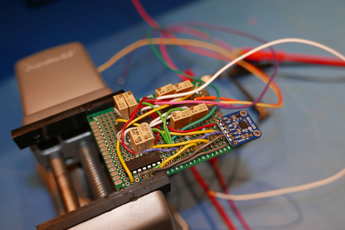
I designed a custom 3-axis accelerometer circuit that plugs into my Holley ECU using the analog 0-5V inputs. It uses a smartphone type chip and I implemented some op-amp circuits to modify and scale the output voltage swings to maximize the digitizing resolution of the Holley ECU which seems to use 12 bit A/D converters. I wanted to get to a +/- 2hp power measurement accuracy which is hard to do. First I changed the output from +/-0.3V/g, to +/-1.0V/g for all axis and then implemented an acceleration only output which is positive 2V/g which I will use specifically for engine power measurements. I will also use the Holley ECU input sensor config settings to further calibrate this unit and finally will have access to the diagnostics 'math channels' to allow me to calculate torque and hp from the raw acceleration and rpm data sets.
I also designed a LiFePO4 battery charging management circuit that sits in-between the standard LiFePO4 14.6V charger and my battery - it was needed to cut off the charging voltage once 14.6V was reached rather than let the battery float at that level which would quickly kill it (you need to get the battery up to 14.6V and then let the internal BMS computer to balance the internal cells and then reduce the voltage back to 13.4V). The circuit I designed also has a continuous use setting which will keep the battery within a 13.4-13.8V operating range when I want to use the battery but not over charge or discharge it. The design uses an Arduino CPU - lots of fun and easy to program.
I am in the middle of designing a new A/C evaporator system using about 1/3 of a Ford F150 evaporator core that now has been plumbed with -8 o-ring fittings and fits nicely on top of my ECU, ultimately feeding into the ventilation fan via a plastic shroud that I will fabricate next - February 7, 2017
3 Axis accelerometer unit ...
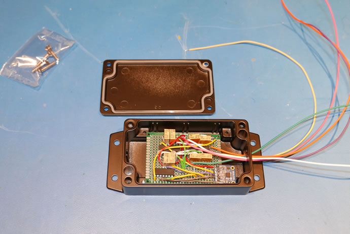
My LiFePO4 battery charging management unit ...
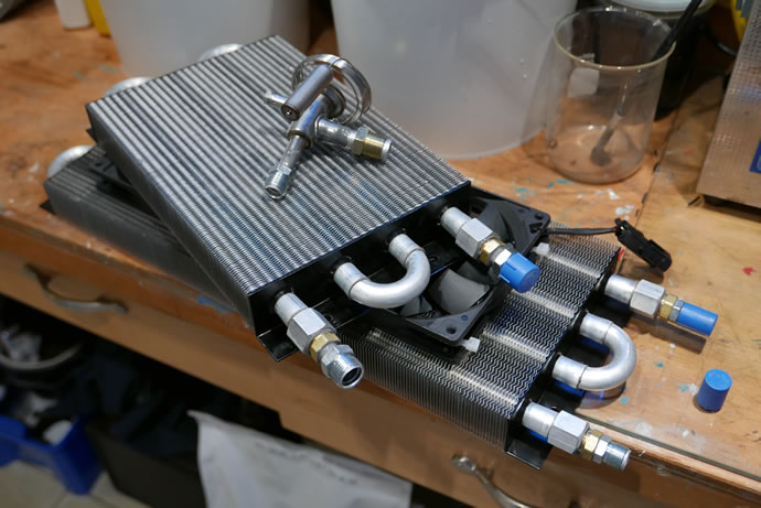
The new A/C evaporator core with -8 fittings installed (using 1/3 of a Ford F150 evaporator core) ...
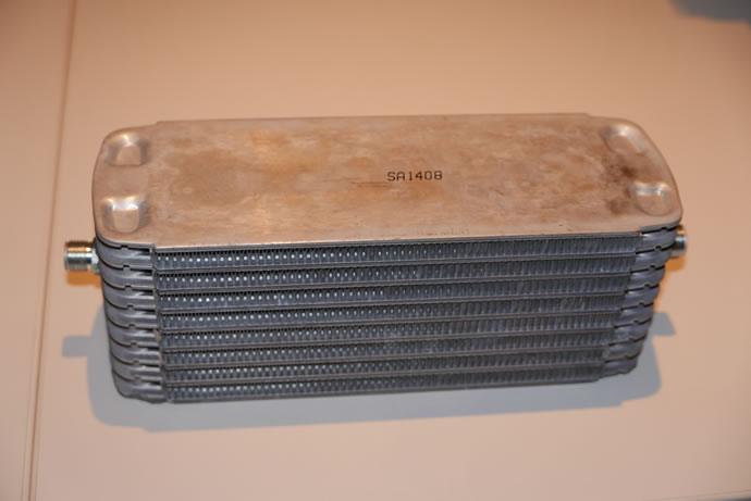

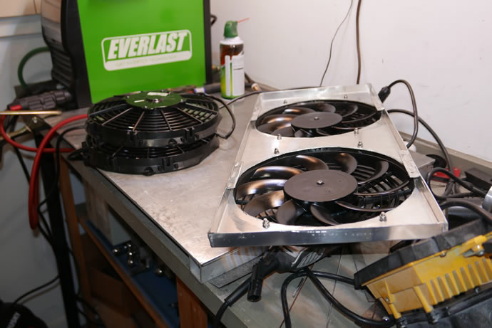
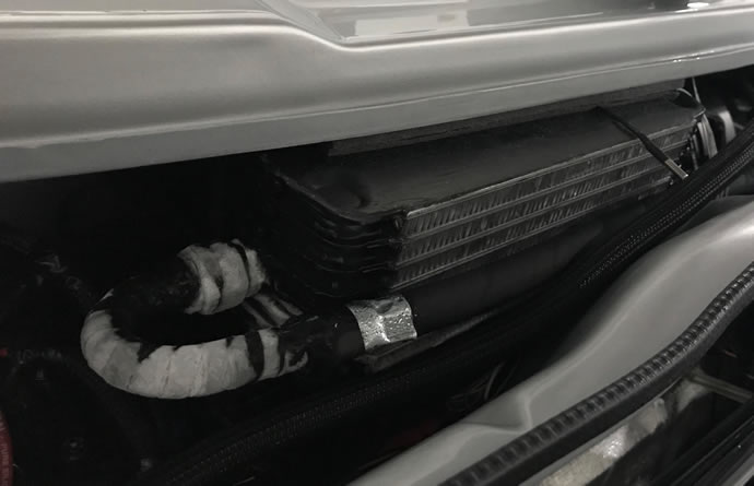
Comparing the old and new condensers - all 6 fans only draw 0.6amps total
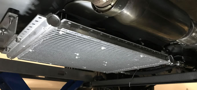
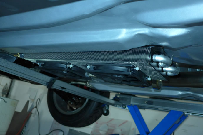
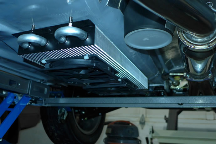
The new a/c condenser mounted under the car - better ground clearance and much higher efficiency than the prior unit
The new evaporator and air ductwork
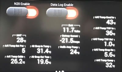
Using R134a refridgerant filled to a 22.5psi low-side pressure with a 31 degree C ambient temperature, there is a 12 degree C air temperature drop across the evaporator which allows for adequate cabin cooling on a hot summer day - think of it as a 'mild' a/c system - my tiny race alternator barely keeps up to the current draw while cruising on the hwy and can't fully keep up in stop and go traffic in the city when the radiator fans have to run to keep the engine cool - but my battery can cover those periods with its LiFePO4 25amp-hour capacity.


My new Philips H4 LED headlights - a nice colour temperature, tons of light output, and a decent cutoff to avoid blinding oncoming traffic
Index of Project web pages:
Project Overview, Goals & Specs
Project Car Initial Condition
Chassis Development
Bodywork & Paint
Suspension, Steering & Braking Systems
Engine, Oiling, Cooling, Transmission & Exhaust Systems
Electrical, A/C & Fuel Systems
Interior
Performance Validation
Final Street Trim Conversion
VW Vortex thread on this project
Videos # 001 - 049 (Feb 2013 - May 2014)
Videos # 050 - 099 (Jul 2014 - Sept 2015)
Videos # 100 - 149 (Sept 2015 - May 2017)
Videos # 150 - 181 (May 2017 - Dec 2019)
My original 1983 Rabbit GTI (owned 1983-1987)